Front body of vehicle

a front body and vehicle technology, applied in the direction of roofs, electric propulsion mountings, jet propulsion mountings, etc., can solve the problem of reducing the degree of design freedom, and achieve the effect of high degree of design freedom

a front body and vehicle technology, applied in the direction of roofs, electric propulsion mountings, jet propulsion mountings, etc., can solve the problem of reducing the degree of design freedom, and achieve the effect of high degree of design freedom

US8894134B2Active Publication Date: 2014-11-25HONDA MOTOR CO LTD

Image

  • Front body of vehicle
  • Front body of vehicle
  • Front body of vehicle

Examples


Embodiment Construction

[0029]Embodiments of the present invention will now be described in detail.

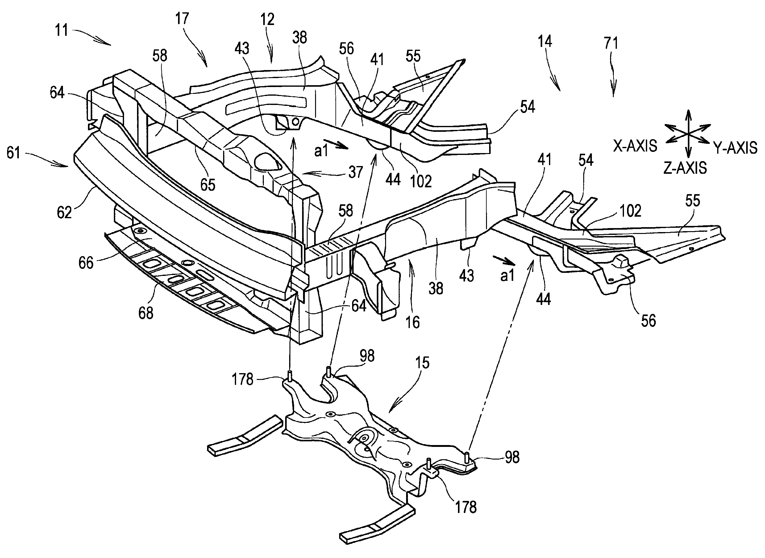
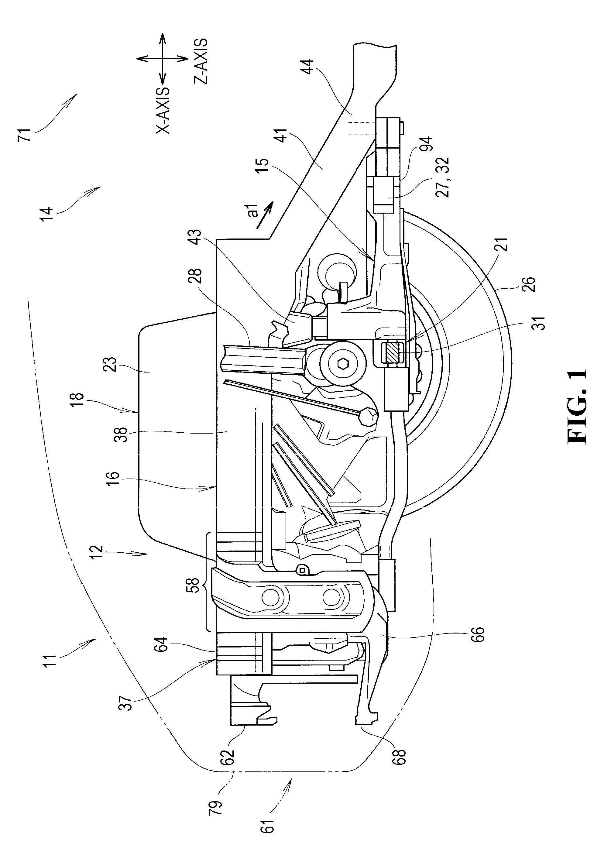
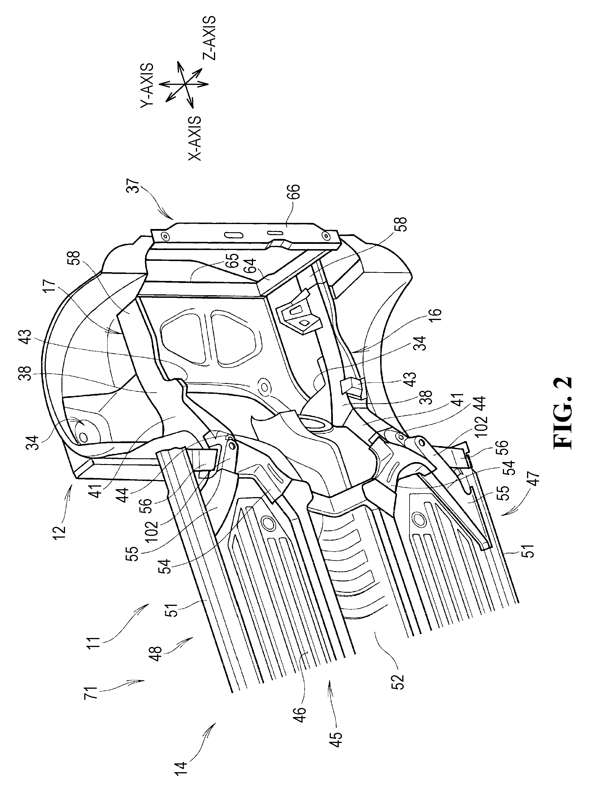
[0030]As illustrated in FIG. 1 to FIG. 3, a vehicle 11 has a front body 12 according to an embodiment. The front body 12 is a front part of a vehicle body 14 and includes a subframe 15. The subframe 15 and left and right front side frames 16 and 17 are configured to hold an engine 18 thereon and support front suspensions 21.

[0031]The front-rear direction of the vehicle 11 is defined as an X-axis direction, the left-right direction (vehicle width direction) of the vehicle 11 is defined as a Y-axis direction, and the up-down direction of the vehicle 11 is defined as a Z-axis direction. Note that the left-right direction is defined with respect to a driver of the vehicle 11, and that the right side of the driver sitting in the driver's seat and facing the front is referred to as “right”.

[0032]As illustrated in FIG. 1, FIG. 5, and FIG. 6, the engine 18 is, for example, a transverse engine (along the Y-axis direct...


PUM


Abstract

A front body of a vehicle is formed by attaching a subframe to left and right front side frames. The subframe is disposed in front of a floor of a cabin and extends to the left and right. An engine contact part facing toward an engine inside the front body is disposed on an upper part the subframe. The subframe has rear fastening parts fastened to the respective front side frames, and rear arm connecting parts with which respective lower arms are engaged. A portion between each of the rear arm connecting parts and the corresponding rear fastening part is deformed to absorb shocks.

Description

CROSS REFERENCES TO RELATED APPLICATIONS[0001]The present application claims priority under 35 U.S.C. §119 to Japanese Patent Application No. 2011-014242, filed Jan. 26, 2011, entitled “Front Body of Vehicle”. The contents of this application are incorporated herein by reference in their entirety.FIELD OF THE INVENTION[0002]The present invention relates to a front body of a vehicle in which lower arms that support respective front wheels are connected to left and right ends of a subframe in front of a floor of a cabin, so that shocks (loads) input to the front of the vehicle are absorbed by the subframe.BACKGROUND OF THE INVENTION[0003]For example, there is a front body of a vehicle in which a subframe is fastened from below to front side members that extend from the front to the rear of the vehicle along respective front wheels. The subframe is substantially rectangular in plan view. The subframe has a rear cross-member positioned near a cabin and extending to the left and right. T...

Claims


Application Information

Patent Timeline
25 Nov 2014
Publication
US8894134B2
IPC
B60K5/00; B62D21/11; B62D21/15; B62D25/08
CPC
B62D21/11; B62D25/082; B62D21/155; B60K5/00
Inventors
TOMOZAWA, KOSAKU; NAKAO, YUSHI