Mist forming method using fluid injection valve, fluid injection valve, and mist forming apparatus

a technology of fluid injection valve and forming apparatus, which is applied in the direction of lighting and heating apparatus, machines/engines, and combustion types, etc., can solve the problems of inability to inject fuel, the shape of the intake port and the intake air flow under the influence thereof is not necessarily optimized, and the effect of increasing the degree of design freedom

Inactive Publication Date: 2013-04-25
MITSUBISHI ELECTRIC CORP
View PDF6 Cites 8 Cited by
  • Summary
  • Abstract
  • Description
  • Claims
  • Application Information

AI Technical Summary

Benefits of technology

[0034]The invention was devised in view of the problems discussed above and has an object to provide a mist forming method using a fluid injection valve, a fluid injection valve, and a mist forming apparatus, each of which achieves both of atomization of a fuel mist and a higher degree of design freedom for a mist shape, a mist pattern, and an injection amount distribution.

Problems solved by technology

Combined with restriction on the layout in an engine room, it is quite difficult to match the three elements always while suppressing adhesion of mist fuel onto an in-cylinder wall surface under various operating conditions.
However, a shape of the intake port and an intake air flow under the influence thereof are not necessarily optimized because of the restriction on the layout in the engine room.
In the case of large- and medium-size two-wheel vehicles, many of the vehicles are incapable of injecting fuel at intake valves because of the layout restriction, and it is not certain which injection system concept is most suitable in this case.
However, many of these engines are single-intake valve engines and actual circumstances is that fuel is injected at the intake valve in some occasions and off the intake valve in the other occasions by one-direction spray (one-stream spray) also because of the layout problem.
None of these proposals, however, describes a measure to achieve both of improvement of atomization of mists and an increase in degree of design freedom for a mist shape, mist pattern, and an injection amount distribution.
Hence, none of these proposals provides a guideline to determine an optimal mist specification in actual circumstances where a shape of the intake port and an intake air flow are different from one engine specification to another.
Hence, applications of this proposal are limited by a shape of the intake port and a location of the intake valve.
There are cases where perfect evaporation and perfect combustion of fuel in the cylinder cannot be expected by only an atomization effect exerted when fuel passes by a channel of the intake valve, and emission of unburnt hydrocarbon (HC) cannot be reduced sufficiently.
In particular, temperatures of the intake port and the intake valve are low immediately after a cold start, and it cannot be expected that mist fuel or adhering fuel in these cold places evaporate soon.
However, Patent Document 2 fails to describe a realization means.
Hence, applications of this proposal are limited by a shape of the intake port and a location of the intake valves.
Even when mists scattered by collision and thereby having a lowered carrying force are pulled by the lead mist injected at the same time and having a high carrying force, timings of behaviors at the tip ends of these mists do not match in time.
This proposal is therefore not suitable for the injection system for gasoline engine that is often in an unsteady state during a transient operation.
This proposal, however, has a problem same as that of Patent Document 2.
It is, however, difficult to maintain a balance in the fuel direction to let the Coanda effect be exerted so that the respective mists do not spread too much on one hand and to suppress the Coanda effect so that the respective mists do not gather on the other hand even under a static atmospheric condition.
Hence, it is quite difficult to implement this proposal in the injection system for gasoline engine that is often in an unsteady state during transient operation.

Method used


Image

  • Mist forming method using fluid injection valve, fluid injection valve, and mist forming apparatus
  • Mist forming method using fluid injection valve, fluid injection valve, and mist forming apparatus
  • Mist forming method using fluid injection valve, fluid injection valve, and mist forming apparatus

Examples


first embodiment

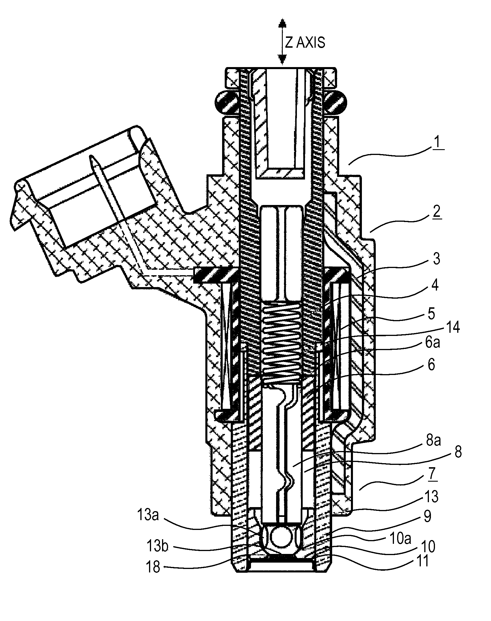
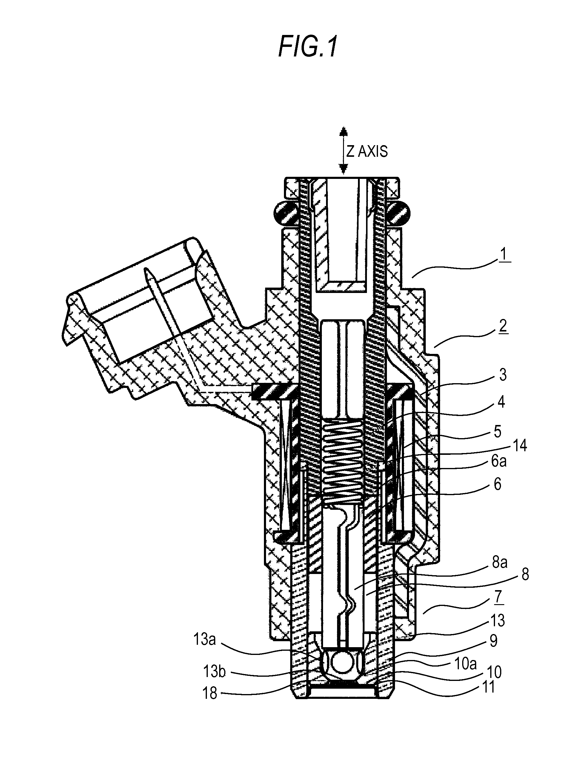
[0065]A fuel injection valve according to a first embodiment of the invention will be described on the basis of FIG. 1 through FIG. 4. FIG. 1 is an overall cross section showing an entire fuel injection valve 1. FIG. 2 is an enlarged view of a tip end of the fuel injection valve 1 shown in FIG. 1. The fuel injection valve 1 is attached to an intake pipe of an internal combustion engine and supplies pressurized fuel toward the intake pipe from above.

[0066]A lower tip end of the fuel injection valve 1 is engaged on the inside of an intake port of the internal combustion engine and injects fuel downward. A solenoid device 2 generating an electromagnetic force is formed of a housing 3 forming a yoke portion of a magnetic circuit, a core 4 forming a fixed iron core, a coil 5 wound around the core 4, and an armature 6 as a movable iron core.

[0067]A valve device 7 joined to the solenoid device 2 is chiefly formed of a valve seat 10 provided inside a valve main body 9 at the tip end portion...

second embodiment

[0092]A second embodiment of the invention will be described using FIG. 6A.

[0093]The second embodiment is characterized in that, as is shown in the cross section taken on line E-E of FIG. 6A, an aspect ratio (ee1 / ee2) of substantially an oval shape or substantially a crescent shape, which are a sectional shape of a jet immediately below each injection hole 12, is set to a value exceeding 1 (preferably, a value equal to or greater than 1.5). When configured in this manner, an area across which the mists oppose each other is increased so that the Coanda effect exerted due to a pressure distribution acts strongly and the mists come closer or gather closer. Then, after the mists appear substantially as one solid mist, the mists are allowed to catch ambient air chiefly based on the momentum theory and thereby to induce an air flow along a downstream flow direction in a predetermined in-mist portion. An injection amount distribution is maintained so as to peak substantially at the center ...

third embodiment

[0094]A third embodiment of the invention will be described using FIG. 8A through FIG. 8D.

[0095]FIG. 8A is a plan view showing an example of an injection hole location when viewed from upstream in a direction of the center axis of the fuel injection valve 1 of a two-stream spray method. The respective injection holes 12b through 12f correspond to a stream of spray on one side of the two-stream spray and data may be different from one injection hole to another. FIG. 8B shows an example of a jet location and a jet shape immediately below the injection holes located as in the example of the injection hole location of FIG. 8A, and jets 12b1 through 12f1 in every adjacent pair are in close proximity to each other. FIG. 8C shows an example of a mist location and a mist shape in the lower stream of the break length position. It shows a state in which respective mists 12b2 through 12f2 gather so as to encircle the surroundings because the respective mists 12b2 through 12f2 are connected in ...


PUM


Abstract

A mist forming method using a fluid injection valve formed of a valve seat, a valve body, and a nozzle portion or an injection hole plate having injection holes, and configured to turn in-hole flows and flows immediately below the injection holes into substantially liquid film flows. Directions of jets from the injection holes are not necessarily brought into coincidence with a center axis direction of the injection holes and are not necessarily crossed with one another in a downstream part, and after the jets turned into mists at a position downstream of a break length position, the mists are allowed to come close or gather by the Coanda effect so as to appear substantially as one solid mist, and allowed to keep gathering until catching of ambient air and a resulting air flow along a downstream flow direction in a predetermined in-mist portion attenuate.

Description

BACKGROUND OF THE INVENTION[0001]1. Field of the Invention[0002]The present invention relates to a mist forming method suitable for a fuel injection valve for internal combustion engine (hereinafter, referred to simply as the engine), a fluid injection valve, and a mist forming apparatus.[0003]2. Background Art[0004]Research and development on engines for vehicle, such as an automobile, are actively conducted to achieve less gas emission when the engine is cold and better fuel consumption by improving combustion characteristics through atomization of a fuel mist.[0005]A fuel injection system of a gasoline engine is classified into a port injection system and an in-cylinder injection system. Three elements important to establish a combustion concept of the in-cylinder injection system are a mist specification (including an injection position), an in-cylinder air flow, and a shape of a combustion chamber. The combustion concept is established only when these elements are well matched....

Claims


Application Information

Patent Timeline
Patent Type & Authority Applications(United States)
IPC IPC(8): B05B1/14
CPCF02M61/184F02M61/186F02M61/1813F02M61/1853F02M61/162F02M61/18F02M61/1806
Inventor SUMIDA, MAMORUNAKAYAMA, TATSUYA
Owner MITSUBISHI ELECTRIC CORP
Why Eureka
Try Eureka