Magnet arrangement for bone conduction hearing implant

a bone conduction and implant technology, applied in the field of medical implants, can solve the problems of affecting the normal position of the magnet or the whole implant housing, and damage to adjacent tissue in the patient,

Active Publication Date: 2014-11-25
MED EL ELEKTROMEDIZINISCHE GERAETE GMBH
View PDF85 Cites 37 Cited by
  • Summary
  • Abstract
  • Description
  • Claims
  • Application Information

AI Technical Summary

Problems solved by technology

One problem with implantable hearing prosthesis systems arises when the patient undergoes Magnetic Resonance Imaging (MRI) examination.
The external magnetic field from the MRI may create a torque on the implant magnet, which may displace the magnet or the whole implant housing out of proper position and / or may damage the adjacent tissue in the patient.
The implant magnet may also cause imaging artifacts in the MRI image, there may be induced voltages in the receiving coil, and hearing artifacts due to the interaction of the external magnetic field of the MRI with the implanted device.
Thus, for existing implant systems with magnet arrangements, it is common to either not permit MRI or at most limit use of MRI to lower field strengths.
But the spherical magnet arrangement requires a relatively large magnet much larger than the thickness of the other components of the implant, thereby increasing the volume occupied by the implant.
This in turn can create its own problems.
This is an additional step during implantation in such applications which can be very challenging or even impossible in case of very young children.

Method used


Image

  • Magnet arrangement for bone conduction hearing implant
  • Magnet arrangement for bone conduction hearing implant
  • Magnet arrangement for bone conduction hearing implant

Examples


Embodiment Construction

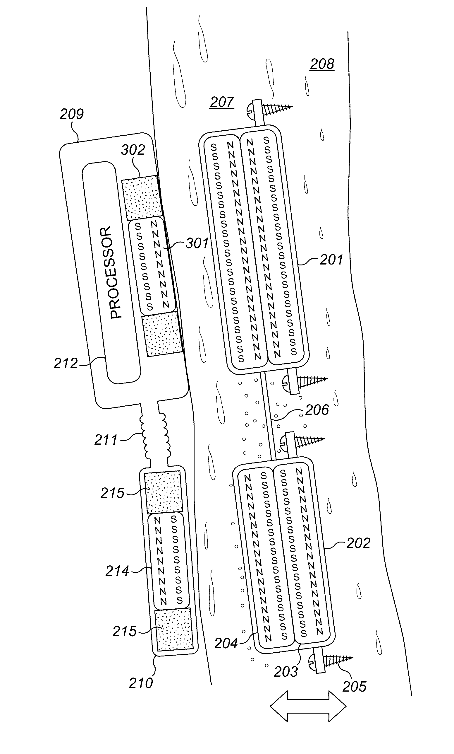
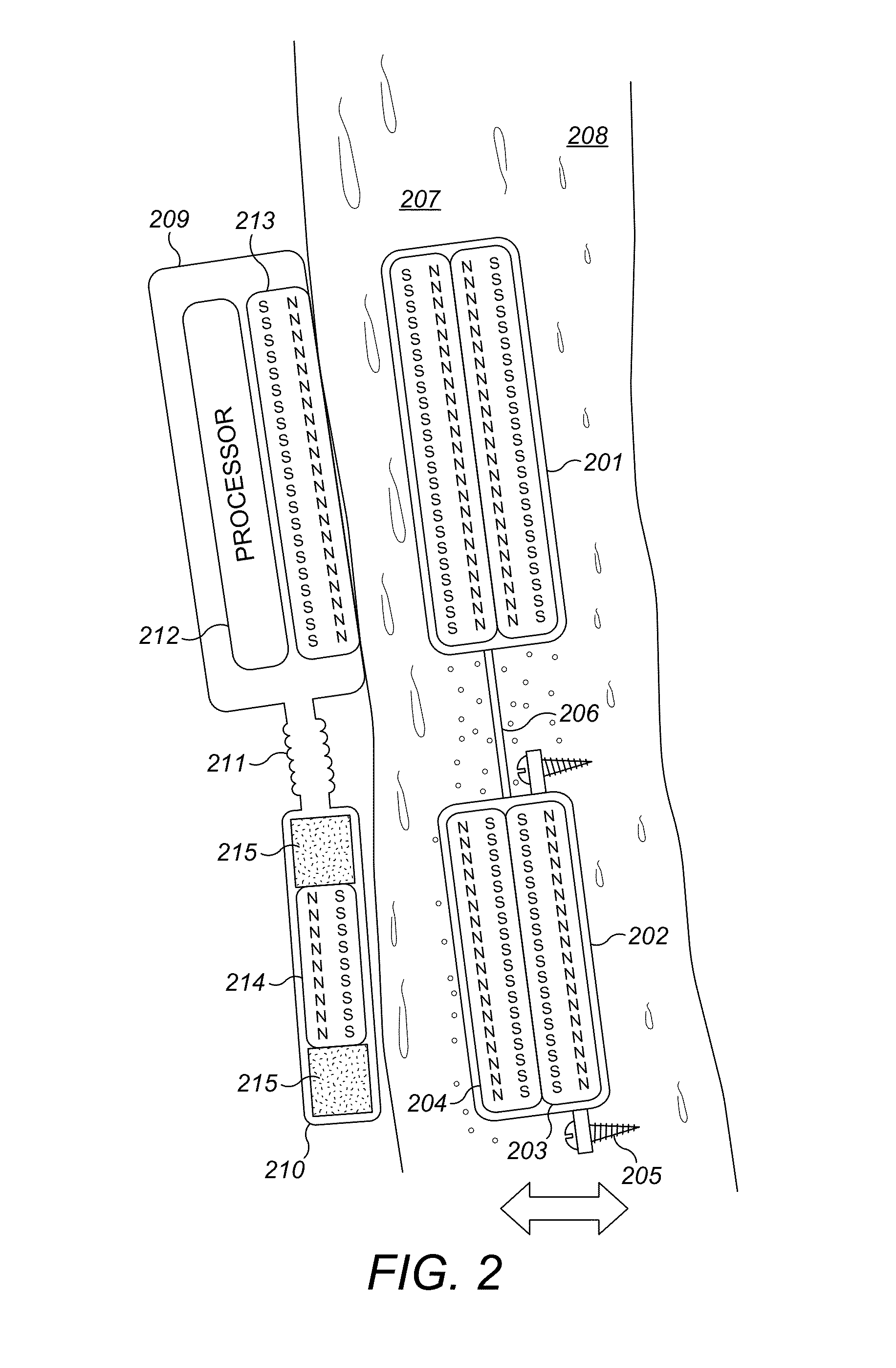
[0018]Embodiments of the present invention are directed to a magnetic arrangement for an implantable hearing prosthesis system which is compatible with MRI systems. FIG. 2 shows a cross-sectional view of an implantable hearing prosthesis arrangement having an implant holding magnet 201 and an implant transducer magnet 202 which are fixable in a common plane beneath the patient skin 207 to underlying skull bone 208. A flexible connector member 206 connects and positions the implant holding magnet 201 and the implant transducer magnet 202 a fixed distance from each other. The implant transducer magnet 202 is fixedly secured to the skull bone 208 by a pair of radially opposed bone screws 205.

[0019]The implant holding magnet 201 and the implant transducer magnet 202 are each enclosed within a titanium housing which contains a pair of internal magnets 203 and 204 in the shape of planar disks that lie in parallel planes which meet along a common junction with repelling like magnetic polar...


PUM


Abstract

An implantable magnet arrangement is described for a hearing implant in a recipient patient. A pair of implant magnets are fixable in a common plane beneath the skin of the patient to underlying skull bone. At least one of the magnets is adapted to transform a magnetic drive signal from an external signal drive coil into a corresponding mechanical stimulation signal for delivery by bone conduction of the skull bone as an audio signal to the cochlea. Each implant magnet includes a pair of internal magnets lying in parallel planes which meet along a common junction with repelling like magnetic polarities facing towards each other, and the magnetic polarities of each implant magnet are reversed from each other.

Description

[0001]This application claims priority from U.S. Provisional Patent Application 61 / 578,953, filed Dec. 22, 2001, which is incorporated herein by reference.FIELD OF THE INVENTION[0002]The present invention relates to medical implants, and more specifically to a novel transcutaneous auditory prosthetic implant system.BACKGROUND ART[0003]A normal ear transmits sounds as shown in FIG. 1 through the outer ear 101 to the tympanic membrane (eardrum) 102, which moves the ossicles of the middle ear 103 (malleus, incus, and stapes) that vibrate the oval window 106 and round window 107 membranes of the cochlea 104. The cochlea 104 is a long narrow duct wound spirally about its axis for approximately two and a half turns. It includes an upper channel known as the scala vestibuli and a lower channel known as the scala tympani, which are connected by the cochlear duct. The cochlea 104 forms an upright spiraling cone with a center called the modiolar where the spiral ganglion cells of the cochlear...

Claims


Application Information

Patent Timeline
Patent Type & Authority Patents(United States)
IPC IPC(8): H04R25/00H04R25/02
CPCH04R25/606H04R25/02H04R2460/13H04R15/00H04R2225/67
Inventor BALL, GEOFFREY R.NAGL, MARKUS
Owner MED EL ELEKTROMEDIZINISCHE GERAETE GMBH
Why Eureka
Try Eureka