Pulse detonation combustor

a combustor and pulse technology, applied in the direction of machines/engines, combustion types, lighting and heating apparatus, etc., can solve the problems of limiting the useful life of such nozzles, limiting the thermal expansion of pulse detonation tubes, and requiring complex mounting and sealing configurations, etc., to facilitate independent thermal expansion of each pulse detonation tub

Inactive Publication Date: 2014-12-02
GENERAL ELECTRIC CO
View PDF6 Cites 23 Cited by
  • Summary
  • Abstract
  • Description
  • Claims
  • Application Information

AI Technical Summary

Problems solved by technology

Unfortunately, due to the high temperatures and pressures associated with detonation reactions, longevity of the pulse detonation tubes and associated components may be significantly limited.
Specifically, nozzles that direct exhaust gas from the pulse detonation tubes to the turbine inlet may experience high thermal stress, thereby limiting the useful life of such nozzles.
In addition, thermal expansion of the pulse detonation tubes requires complex mounting and sealing configurations to maintain an entrance angle of exhaust gas into the turbine and efficiency of the turbine engine.

Method used


Image

  • Pulse detonation combustor
  • Pulse detonation combustor
  • Pulse detonation combustor

Examples


Embodiment Construction

[0017]One or more specific embodiments of the present invention will be described below. In an effort to provide a concise description of these embodiments, all features of an actual implementation may not be described in the specification. It should be appreciated that in the development of any such actual implementation, as in any engineering or design project, numerous implementation-specific decisions must be made to achieve the developers' specific goals, such as compliance with system-related and business-related constraints, which may vary from one implementation to another. Moreover, it should be appreciated that such a development effort might be complex and time consuming, but would nevertheless be a routine undertaking of design, fabrication, and manufacture for those of ordinary skill having the benefit of this disclosure.

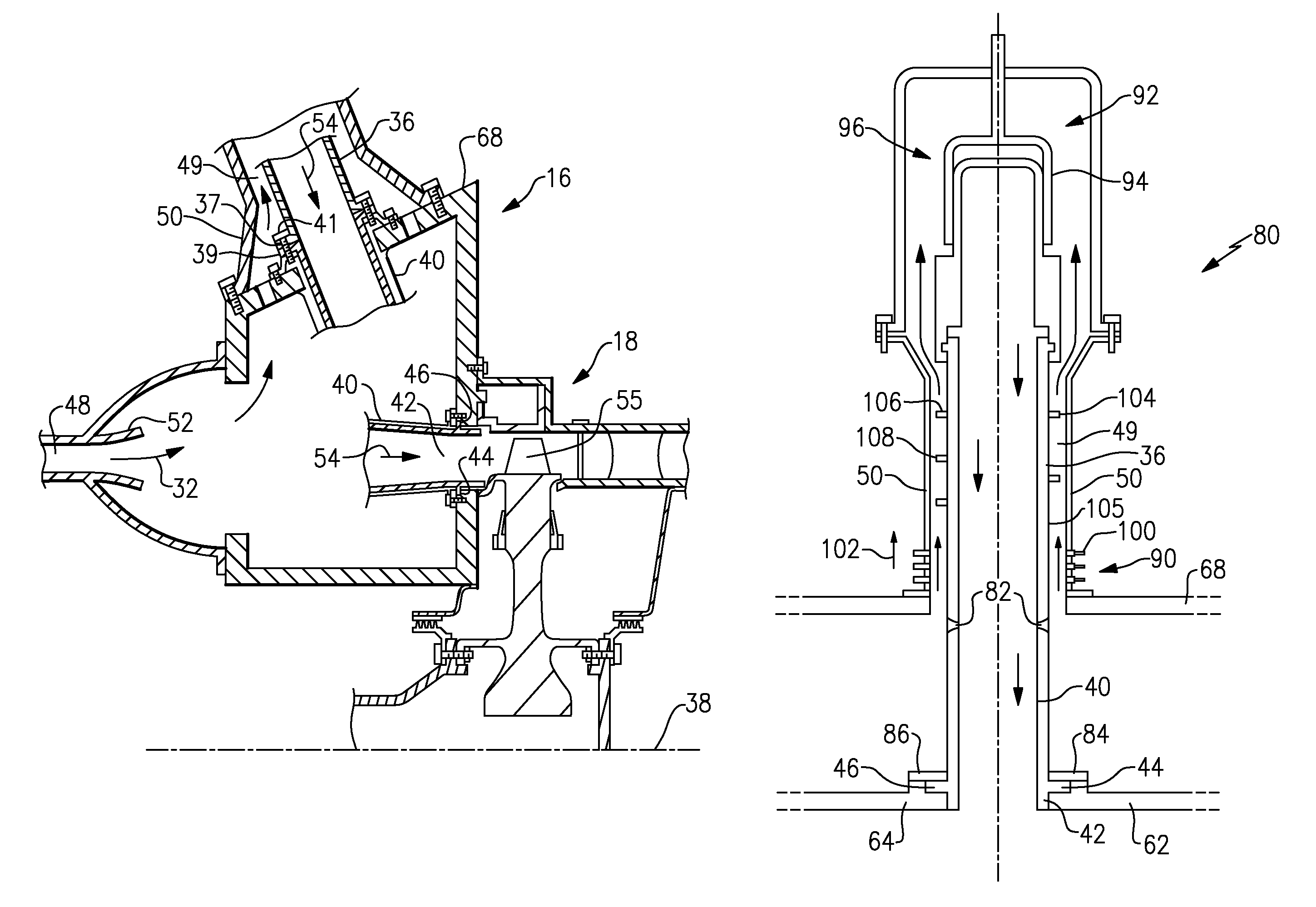
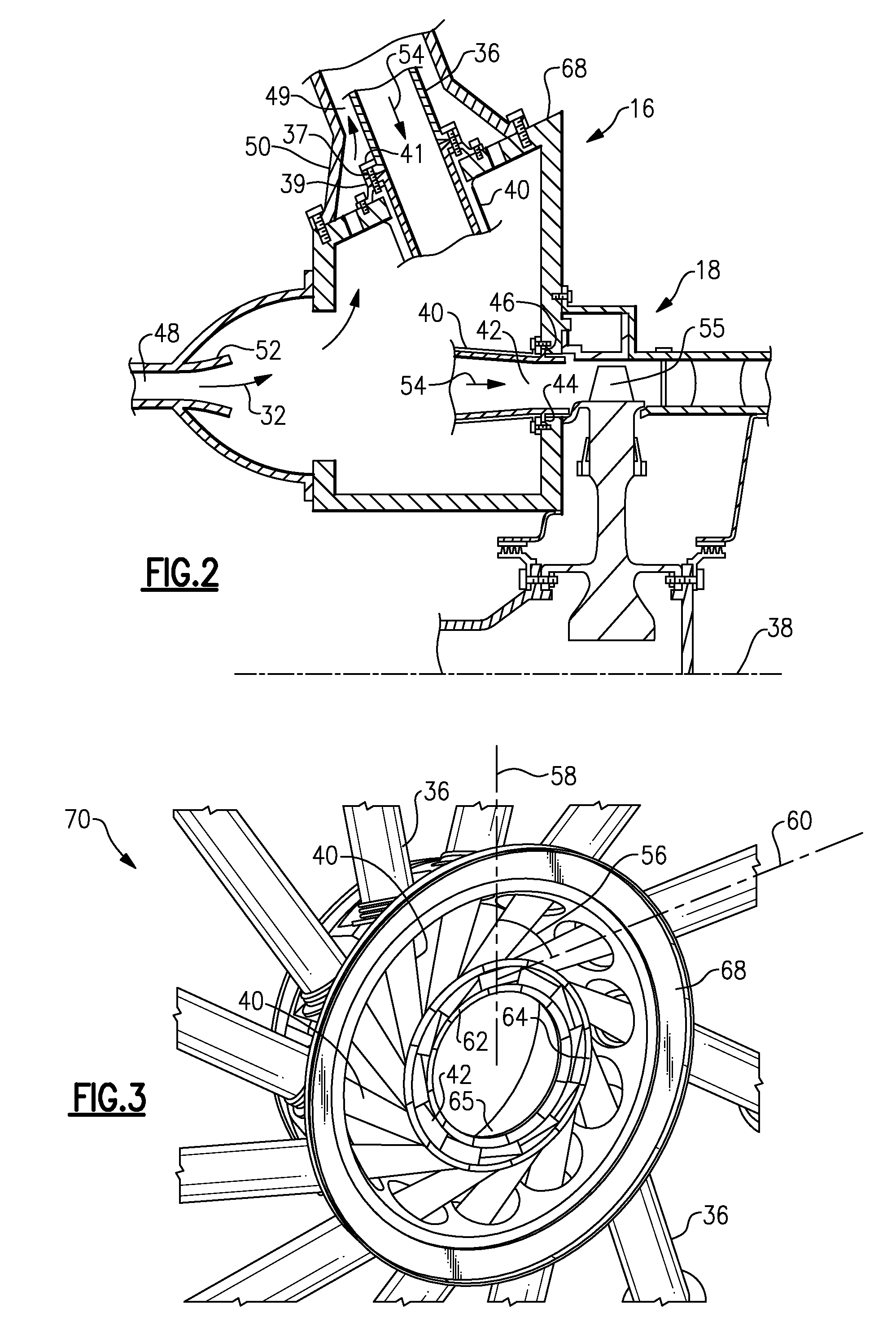
[0018]Embodiments of the present disclosure may increase the longevity of pulse detonation combustors, and in particular the pulse detonation tubes, by...


PUM


Abstract

A pulse detonation combustor including a plurality of nozzles engaged with one another via mating surfaces to support a gas discharge annulus in a circumferential direction. The pulse detonation combustor also including multiple pulse detonation tubes extending for the nozzles and a plurality of thermal expansion control joints coupled to the plurality of pulse detonation tubes. Each of the plurality of thermal expansion control joints is configured to facilitate independent thermal growth of each of the plurality of pulse detonation tubes. The thermal expansion control joints may be configured as a bellows expansion joint or a sliding expansion joint.

Description

BACKGROUND[0001]The subject matter disclosed herein relates to a pulse detonation combustor, and, more specifically, to an arrangement of pulse detonation tubes within a pulse detonation combustor that accommodates thermal growth of the pulse detonation tubes.[0002]Gas turbine engines include one or more combustors, which receive and combust compressed air and fuel to produce hot combustion gases. Certain turbine engine concepts employ a pulse detonation combustor that includes one or more pulse detonation tubes configured to combust the fuel-air mixture using a detonation reaction. Within a pulse detonation tube, the combustion reaction is driven by a detonation wave that moves at supersonic speed, thereby increasing the efficiency of the combustion process. Specifically, air and fuel are typically injected into the pulse detonation tube in discrete pulses. The fuel-air mixture is then detonated by an ignition source, thereby establishing a detonation wave that propagates through t...

Claims


Application Information

Patent Timeline
Patent Type & Authority Patents(United States)
IPC IPC(8): F02C5/00F23R7/00F02C7/20F02C5/02
CPCF23D2211/00F02C5/02F23R7/00F05D2260/16
Inventor KENYON, ROSS HARTLEYRASHEED, ADAMDOM, JR., PAUL WHITSONPOMBLES, MARK JOSEPH
Owner GENERAL ELECTRIC CO
Why Eureka
Try Eureka