Light source fixing device, light source assembly and assembling method thereof

a technology for fixing devices and light sources, applied in the field of display, can solve the problems of significantly degrading the heat dissipation efficiency, and reducing the contact area, so as to simplify the assembling process, reduce the number of components to be assembled, and improve the reliability of the product.

Inactive Publication Date: 2014-12-02
TCL CHINA STAR OPTOELECTRONICS TECH CO LTD
View PDF16 Cites 2 Cited by
  • Summary
  • Abstract
  • Description
  • Claims
  • Application Information

AI Technical Summary

Benefits of technology

[0010]In view of the problem that the aforesaid light source assembly requires a complex assembling process and has low reliability and a high cost, embodiments of the present invention provide a light source fixing device that features a simple assembling process, high reliability and a low cost, and further provide a light source assembly and an assembling method thereof.
[0025]In the light source fixing device and the light source assembly of the embodiments of the present invention, the receiving recess is directly disposed on the surface of the heat dissipating support as a holding structure, which can effectively fix the supporting plate and ensure that the supporting plate and the light source have the same relative positions relative to the heat dissipating support; meanwhile, the elastic element is additionally provided to elastically fix the supporting plate so as to prevent the supporting plate and the heat dissipating support from loosening and falling off. This can improve the reliability of the product and also avoid use of locking elements such as screws, thus reducing the number of elements to be assembled and simplifying the assembling process.

Problems solved by technology

Due to the phenomenon of thermal expansion and contraction effect, the whole PCB 13 tends to be deformed to cause a loose contact between the PCB 13 and the heat sink 15, which reduces the contact area and significantly degrades the heat dissipation efficiency.
Furthermore, as assembled by use of screws, usually a tight fit cannot be achieved between the PCB 13 and the heat sink 15 due to inaccurate aligning operations performed by workers; which also reduces the contact area and significantly degrades the heat dissipation efficiency.
More importantly, the use of the screwed structure leads to a large number of elements, a complex assembling process and an increased cost of the whole light source assembly 1.
In the light source assembly 2, although the use of the thermally conductive adhesive layer 24 simplifies the whole structure and the assembling process, there still exists the following problem: when the light source assembly 2 operates, the temperature of the thermally conductive colloid layer 24 increases with the temperature of the whole assembly, which causes aging and degradation in the adhesive performance of the chemical material of the thermally conductive colloid layer 24; this tends to cause loosing and falling off of the PCB 23 and the heat sink 25 from each other, thereby resulting in degraded heat dissipating performance and reliability of the product.

Method used


Image

  • Light source fixing device, light source assembly and assembling method thereof
  • Light source fixing device, light source assembly and assembling method thereof
  • Light source fixing device, light source assembly and assembling method thereof

Examples


first embodiment

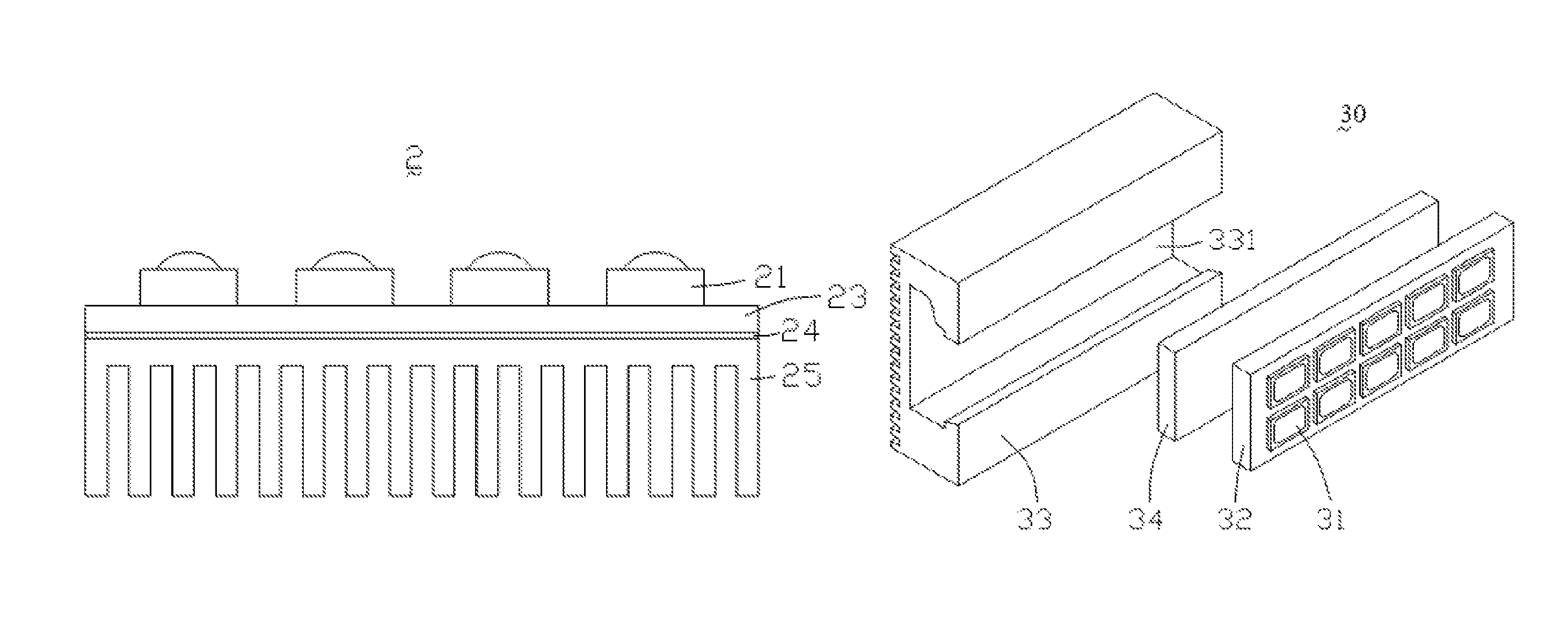
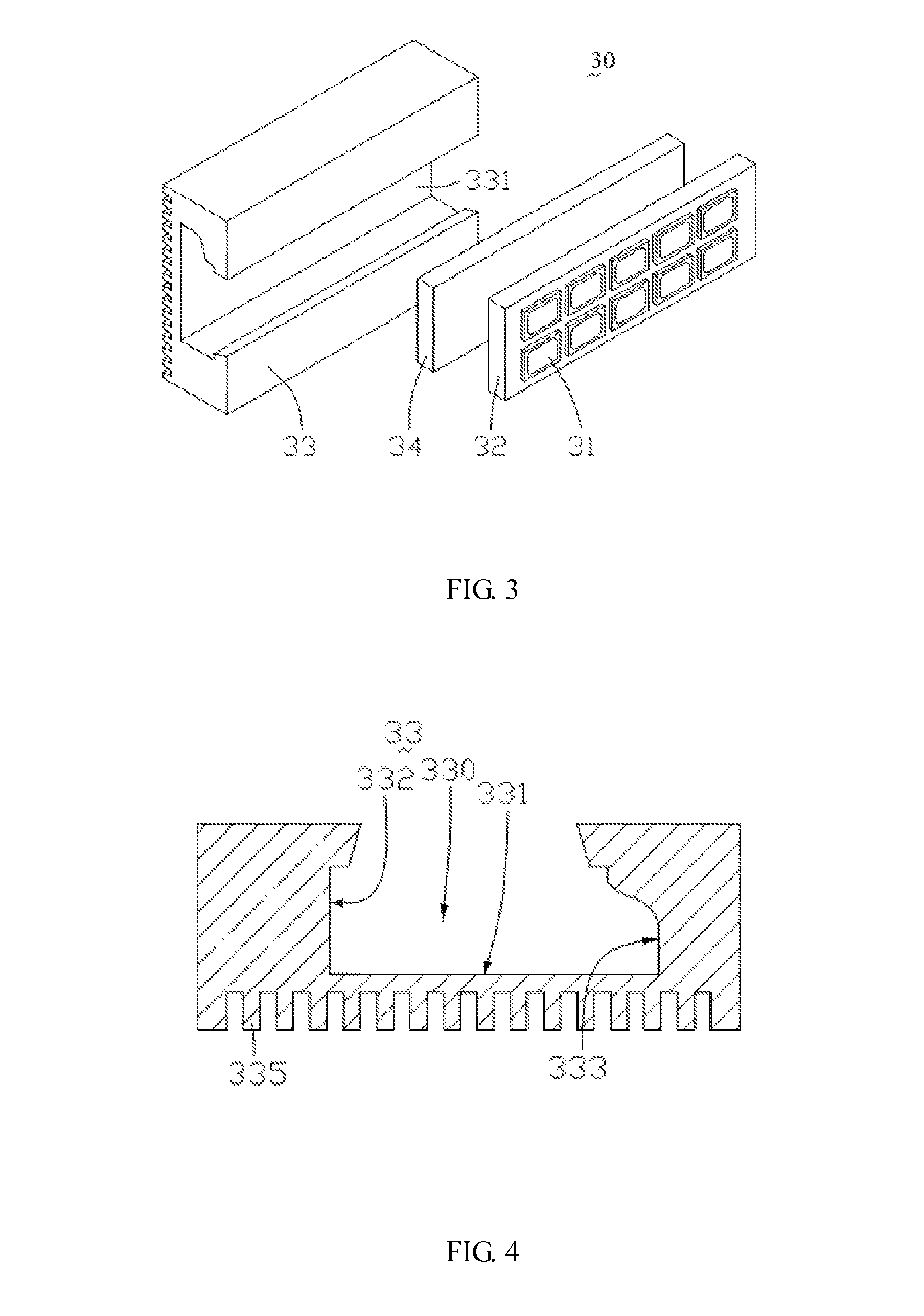
[0037]Referring to FIG. 3, a light source assembly 30 according to the present invention comprises a plurality of LEDs 31, a circuit board 32, a heat dissipating support 33 and an elastic element 34. The LEDs 31 and the circuit board 32 are collectively called a light emitting element.

[0038]The LEDs 31 are arranged in an array on a side surface of the circuit board 32. Each of the LEDs 31 is a point light source electrically connected to the circuit board 32. The circuit board 32 is a rigid printed circuit board (PCB) or a flexible PCB having a plurality of pads (not shown) and a printed circuit (not shown) disposed on a surface thereof. The pads are arranged in an array. Each of the pads corresponds to one of the LEDs 31; i.e., the LED 31 is welded onto the pad of the circuit board 32, correspondingly. The printed circuit on the surface of the circuit board 32 transmits an electric signal to the LED 31 via the pad to drive the LED 31. When the LEDs 31 arranged in an array operate, ...

second embodiment

[0045]FIG. 5 is a cross-sectional view of a light source assembly 30′ according to the present invention. Similar to the light source assembly 30 of FIG. 3, the light source assembly 30′ also comprises LEDs 31′, a circuit board 32′, a heat dissipating support 33′ and an elastic element 34′. The difference lies in that, in this embodiment, the LEDs 31′ are arranged in one row and the heat dissipating support 33′ is not formed with heat dissipating fins on a bottom thereof.

[0046]The present invention further provides an assembling method of a light source assembly, which mainly comprises a placing step and a pressing step. In the placing step, a supporting plate of a light emitting element is placed into a receiving recess of a heat dissipating support via an opening of the receiving recess. In the pressing step, the supporting plate is used to press an elastic element in the receiving recess to cause elastic deformation of the elastic element and to have the supporting plate of the l...

third embodiment

[0050]Referring to FIG. 7 and FIG. 8 together, FIG. 7 is a schematic perspective view of a structure of a light source assembly according to the present invention, and FIG. 8 is a schematic view showing an assembling process flow of the light source assembly of FIG. 7.

[0051]The light source assembly 40 is substantially the same as the light source assembly 30 in the first embodiment 30 except that: a plurality of grooves 431 is further formed at the opening of the receiving recess 430 of the light source assembly 40, a plurality of protrusions 421 is formed correspondingly at two sides of the circuit board 42, and the protrusions 421 have a profile matching with a profile of the grooves 431. When the light source assembly 40 is assembled, a light emitting element with the protrusions 421 at sides thereof is firstly placed into the opening of the receiving recess 430 in such a way that the protrusions 421 are disposed into the grooves 431; then the elastic element 44 in the receiving...


PUM

PropertyMeasurementUnit
elasticaaaaaaaaaa
widthaaaaaaaaaa
thermally conductiveaaaaaaaaaa

Abstract

The present invention provides a light source fixing device for fixing a light emitting element. The light emitting element comprises a light source and a supporting plate for supporting the light source. The light source fixing device comprises a heat dissipating support which comprises a receiving recess. The receiving recess is adapted to receive the supporting plate. The light source fixing device further comprises an elastic element disposed in the receiving recess, and the elastic element is adapted to apply an elastic force on the supporting plate so that the supporting plate is fixed in the receiving recess. The present invention further provides a light source assembly and an assembling method thereof. The light source assembly features a simple assembling process, high reliability and a low cost.

Description

TECHNICAL FIELD[0001]The present invention generally relates to the field of display, and more particularly, to a light source fixing device, a light source assembly and an assembling method of the light source assembly.BACKGROUND[0002]With rapid development of the electronic product technologies, light emitting diodes (LEDs) have found increasingly wider application in, for example, the field of LED illumination, the field of liquid crystal display (LCD) and various industrial control display apparatuses.[0003]In the field of liquid crystal display, a liquid crystal display device usually comprises a backlight module and a liquid crystal display panel superposed thereon. The liquid crystal panel cannot emit light by itself, so the backlight module is used as a light source in the liquid crystal display for driving the liquid crystal display panel display images. As a kind of typical point light source device, LEDs are often used in the backlight module as a key component. usually, ...

Claims


Application Information

Patent Timeline
Patent Type & Authority Patents(United States)
IPC IPC(8): F21V19/00F21V29/00
CPCF21V19/0045Y10T29/49872
Inventor LIN, PO-LEMQUE, CHENGWEN
Owner TCL CHINA STAR OPTOELECTRONICS TECH CO LTD
Why Eureka
Try Eureka