Wind turbine yaw system and method of controlling the same

a technology of wind turbines and yaws, which is applied in the direction of wind energy generation, liquid fuel engine components, non-positive displacement fluid engines, etc., can solve the problems of unfavorable wind energy generation, and uneven wear and tear of mechanical components of drive motors and transmissions, so as to achieve more evenly distributed loads

Active Publication Date: 2014-12-02
SIEMENS GAMESA RENEWABLE ENERGY AS
View PDF18 Cites 11 Cited by
  • Summary
  • Abstract
  • Description
  • Claims
  • Application Information

AI Technical Summary

Benefits of technology

[0005]It is therefore an objective of the present invention to provide a wind turbine yaw system which allows for more evenly distributing the loads over drive units in a yaw system. It is a further objective to provide an advantageous wind turbine. It is a still further objective of the present invention to provide a method for controlling the drive units in a yaw system which allows to more evenly distribute the loads over the drive units.

Problems solved by technology

However, such a configuration represents mechanically connected motors which can lead to load sharing issues like different loads experienced by the motors not only when motors of different sizes are used but also when motors of the same size are used which have slightly different characteristics.
This in turn induces unequal tear and wear of the mechanical components of the drive motors and the transmissions.

Method used


Image

  • Wind turbine yaw system and method of controlling the same
  • Wind turbine yaw system and method of controlling the same
  • Wind turbine yaw system and method of controlling the same

Examples


Embodiment Construction

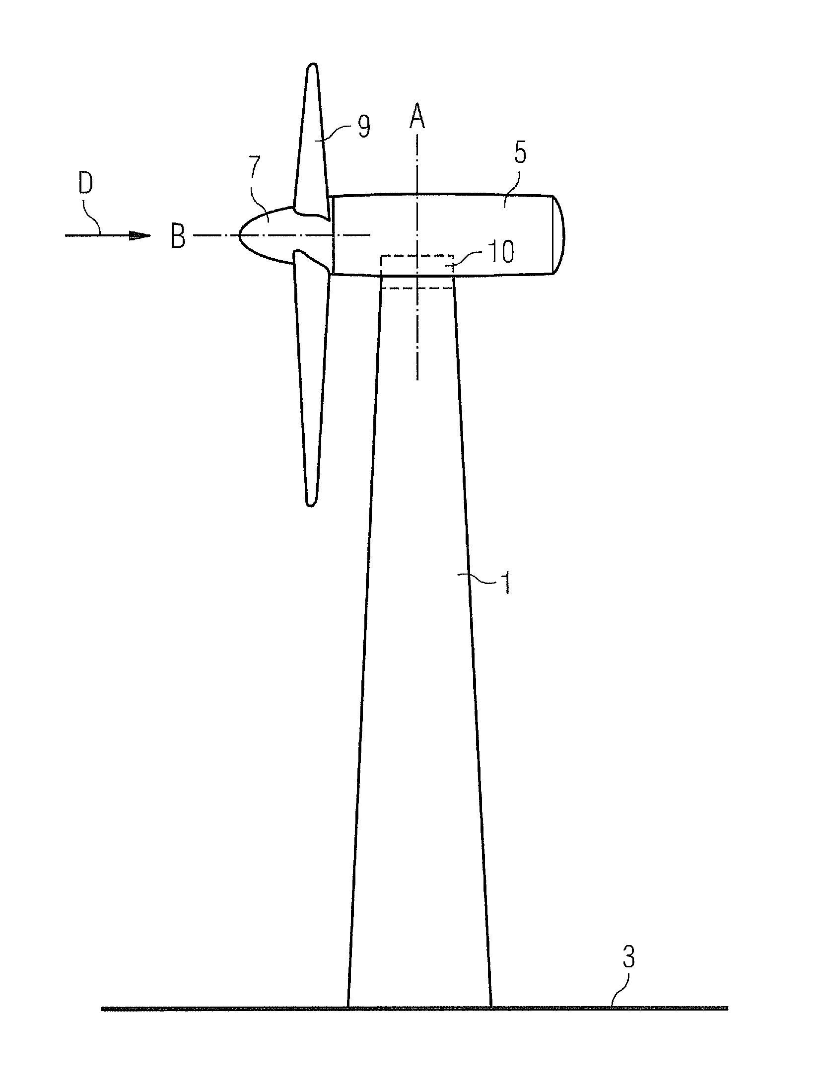
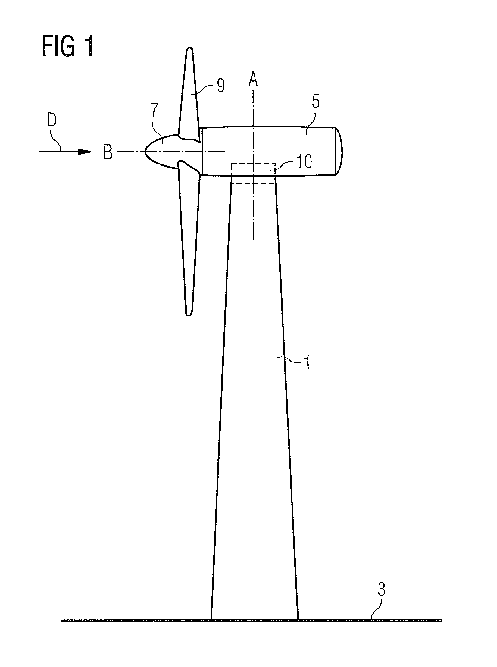
[0025]A typically wind turbine is shown in FIG. 1. The wind turbine 1 comprises a tower 1 which rests on a fundament in the ground 3. At the top of the tower 1, a nacelle 5 is located which carries a rotor 7 driven by the wind. Typically the rotor comprises three rotor blades 9 arranged in angles of 120°. Other rotor designs with more or less than three rotor blades are possible, for example two bladed rotors or even one bladed rotors. However, two bladed rotors and, in particular, three bladed rotors are most commonly used.

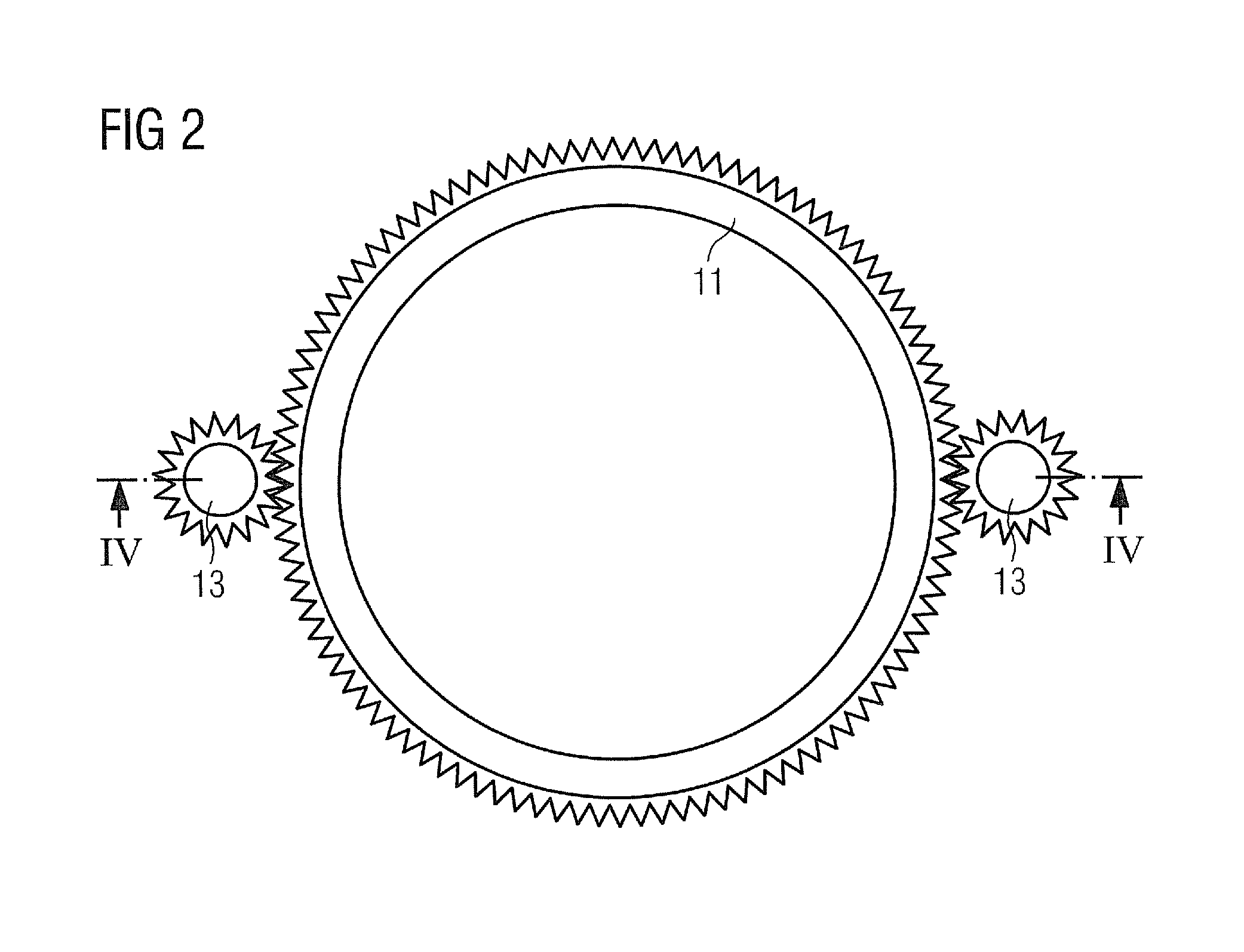
[0026]A yaw drive 10 is arranged between the nacelle 5 and the tower 1 for allowing the nacelle 5 to be rotated about a tower axis A so as to bring the rotor axis B into alignment with the wind direction D and keep the rotor axis B aligned with the wind direction D. A typical yaw drive 10 is schematically shown in FIG. 2 in a plan view. It comprises a ring gear 11 which is typically located at the tower top and a number of pinion gears 13 located at the nacelle 5...


PUM


Abstract

A wind turbine yaw system is provided that includes a yaw gear, at least two pinion gears, and at least two drive units, each of which is associated to one of the pinion gears for driving that pinion gear. The yaw system also includes a control system with a controller for generating a drive unit control signal for each drive unit for controlling the respective drive unit according to a reference signal having a desired operational parameter value for the respective drive unit, so as to realize the desired operational parameter value in the respective drive unit. The control system includes a feedback loop for each drive unit feeding a drive unit feedback signal including at least the actual value of one operational parameter of the respective drive unit back to the controller. The controller generates the drive unit control signals based on the reference signal and the feedback signals.

Description

CROSS REFERENCE TO RELATED APPLICATIONS[0001]This application claims priority of European Patent Office application No. 10167623.7 EP filed Jun. 29, 2010, which is incorporated by reference herein in its entirety.FIELD OF INVENTION[0002]The present invention relates to a wind turbine yaw system with a yaw gear, at least two pinion gears and at least two drive units where each drive unit is associated to one of the pinion gears. In addition, the invention relates to a control method for such a wind turbine yaw system.BACKGROUND OF INVENTION[0003]A wind turbine yaw system is located between the nacelle and the tower of a wind turbine and serves for rotating the rotor of the wind turbine about the tower axis. It typically comprises a gear assembly with a ring gear fixed to the tower and at least one motor driven pinion gear fixed to the nacelle. Usually, at least two motor driven pinion gears are present for realizing a more even load distribution over the ring gear. An example for a w...

Claims


Application Information

Patent Timeline
Patent Type & Authority Patents(United States)
IPC IPC(8): F03D7/04F03D7/02
CPCF05B2260/74F05B2270/1032F03D7/0204Y02E10/723F05B2240/40Y02E10/72
Inventor ANDERSEN, KURT
Owner SIEMENS GAMESA RENEWABLE ENERGY AS
Why Eureka
Try Eureka