Ethylene cracking furnace with multi-pass radiant coil

a technology of radiant coil and cracking furnace, which is applied in the field of petrochemical engineering, can solve the problems of lowering the lifetime of the radiant coil, reducing the temperature of the tube wall, and extending the operation cycle of the furnace, so as to reduce the heat radiation influence reduce the temperature of the high-temperature tube surface, and compact structure

Active Publication Date: 2014-12-02
CHINA PETROCHEMICAL CORP +2
View PDF14 Cites 0 Cited by
  • Summary
  • Abstract
  • Description
  • Claims
  • Application Information

AI Technical Summary

Benefits of technology

[0009]Considering the defects in the prior arts, the present invention aims to provide an ethylene cracking furnace having a multi-pass radiant coil, which includes a novel tube arrangement that can improve the heating condition so as to enable the tubes being heated more evenly. In addition, the present invention further aims to provide an ethylene cracking furnace having a multi-pass radiant coil, which can enhance the mechanical properties of the radiant coil, increase the on-line percentage of the cracking furnace, reduce the operation cost, and extend the lifetime of the coil and the operational cycle of the cracking furnace.
[0011]It should be noted that with regard to the first tube, the tube consecutive thereto is the second tube; with regard to the second tube, the tubes consecutive thereto are the first tube and the third tube, and so on. With at least one tube of the multi-pass radiant coil being arranged to be spatially adjacent to a tube which is not consecutive to the at least one tube, said at least one tube can be spatially adjacent to a tube having a temperature not close to that of said at least one tube. Therefore, the even temperature distribution within the radiant section can be effectively improved. Consequently, the surface temperature of the radiant coil can be lowered, and thus the lifetime of the radiant coil and the operational cycle of the cracking furnace can both be extended.
[0012]According to an embodiment of the present invention, the last two tubes of the multi-pass radiant coil are arranged to be spatially non-adjacent to each other. Since the last two tubes have the highest temperatures among all tubes, the thermal radiation influence from the high-temperature tubes can be effectively reduced. Therefore, the surface temperature of the radiant coil can be further lowered, and thus both the lifetime of the radiant coil and the operational cycle of the cracking furnace can be further extended.
[0014]According to one embodiment of the present invention, the tubes of the multi-pass radiant coil are connected with each other by means of connectors. Since the temperatures on the walls of the tubes in the multi-pass radiant coil are different from each other, the thermal expansion between two adjacent tubes will be different, thus resulting in thermal stress. In one example, at least one connector located in the lower part of the radiant section is a combined connector consisting of a U-shaped elbow and two S-shaped elbows located at the opposite sides of the U-shaped elbow respectively. With the above combined connector consisting of S-shaped elbows and U-shaped elbow, the thermal stress generated from heating and uneven burning at the opposite outer sides of the coil can be absorbed. Accordingly, tube bending due to the thermal stress resulted from any possible reasons can be prevented. In this way, the mechanical properties of radiant coil are effectively improved. Consequently, partial overheating due to tube bending can be avoided, and thus both of the lifetime of the radiant coil and the operational cycle of the cracking furnace can be extended.
[0015]In one example, the tubes in the central plane of the radiant section are arranged as not being spatially adjacent to each other, and at both sides of the central plane there are provided with equal quantity of S-shaped elbows connected by a U-shaped elbow. In such an arrangement, the temperature in the radiant section is more evenly distributed, and the distortion caused by thermal stress can be more evenly absorbed. These S-shaped elbows have downward projections parallel to each other, or at least one of them has a downward projection is not parallel to downward projections of the others due to structural requirements. Likewise, all U-shaped elbows can also have downward projections parallel to each other. These arrangements are advantageous for obtaining a very compact structure.
[0018]The present invention presents the following advantages over the prior arts: (i) since the high-temperature tubes and the low-temperature tubes are arranged alternately or in a form of partial interleaving arrangement, the heat radiation influence from the high-temperature tubes can be reduced, and the tubes with low temperature can absorb the heat from those with high temperature; as a result, the temperature of surface of the high-temperature tubes can be lowered, and both of the lifetime of the radiant coil and the operational cycle of the cracking furnace can be extended; and (ii) by using combined connectors other than common elbows to connect the bottoms of the tubes, the mechanical properties of the radiant coil can be significantly improved, which is advantageous for absorbing thermal stress generated by temperature differences between two adjacent tubes, thus preventing the tubes from bending due to the thermal stress, avoiding partial overheating due to tube bending, and eventually extending both the operation cycle of the cracking furnace and the lifetime of the radiant coil.

Problems solved by technology

Moreover, radiant heat exchange will also exist between the high-temperature tubes, i.e., the third and the fourth tubes in this case, which would negatively influence on reducing the tube wall temperature and extending the operation cycle of the furnace.
This is undesirable for absorption of heat expansion generated in each of these tubes.
In a long time operation, it will easily lead to bending of tubes, lowering the lifetime of the radiant coil and therefore shortening the operation cycle thereof.

Method used


Image

  • Ethylene cracking furnace with multi-pass radiant coil
  • Ethylene cracking furnace with multi-pass radiant coil
  • Ethylene cracking furnace with multi-pass radiant coil

Examples


Embodiment Construction

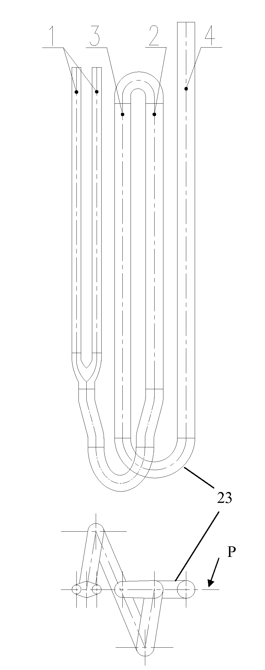
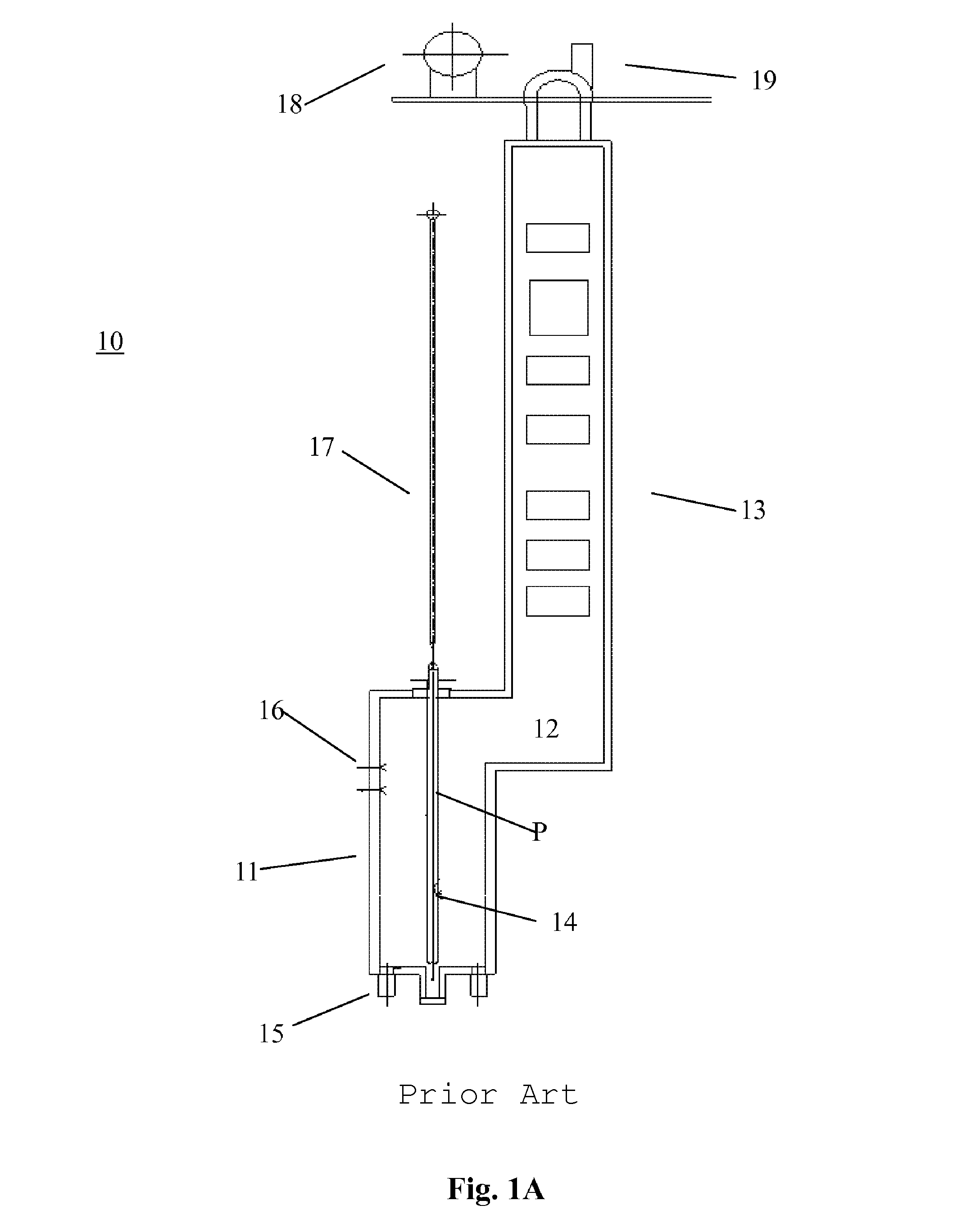
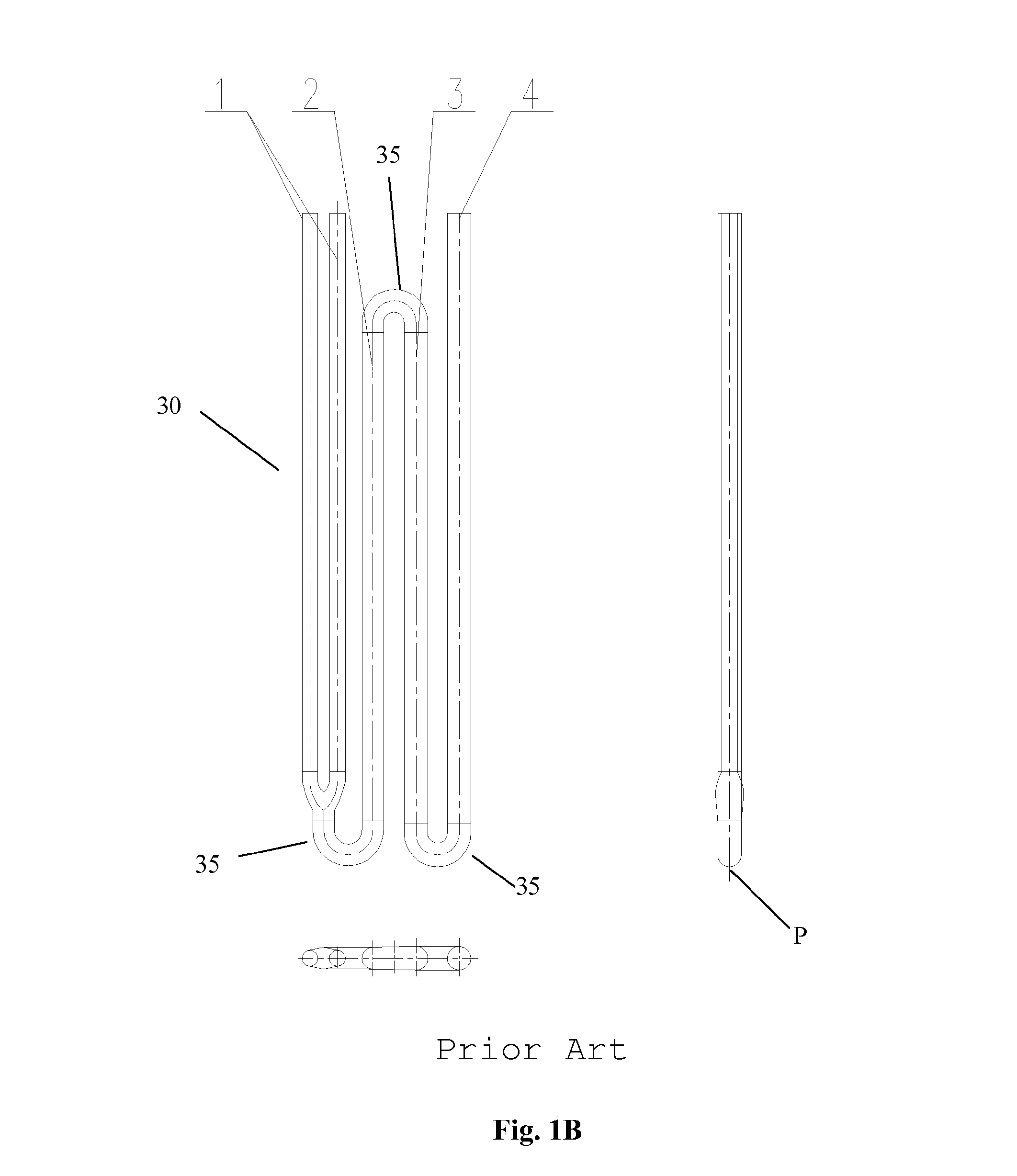
[0026]In the following the present invention will be discussed in details with reference to the accompanying drawings. It should be noted that the present invention aims to provide improvements on radiant coil in the radiant section of the ethylene cracking furnace. Other structures in the ethylene cracking furnace, such as the convective section, the transfer line exchanger and the like, are already known in the prior art. For example, the transfer line exchanger suitable for the present invention can be double-coil transfer line exchanger (such as linear transfer line exchanger, U-type transfer line exchanger and the first level of two-level transfer line exchanger, etc.), conventional boiler, bath boiler or quick transfer line exchanger. Moreover, the radiant coil of the present invention can be suitable for cracking gas material and liquid material, and can be used in building new cracking furnaces or reconstructing existing cracking furnaces. These are known to one ordinarily s...


PUM

PropertyMeasurementUnit
diametersaaaaaaaaaa
diameteraaaaaaaaaa
temperatureaaaaaaaaaa

Abstract

The invention relates to an ethylene cracking furnace having a multi-pass radiant coil, comprising at least one radiant section. In the radiant section there are provided with bottom burners and / or sidewall burners, and at least one set of multi-pass radiant coil longitudinally arranged in the radiant section. The multi-pass radiant coil is a four- to ten-pass type radiant coil. At least one tube of the multi-pass radiant coil is arranged to be spatially adjacent to a tube which is not consecutive to said at least one tube. With this arrangement, the thermal radiation influence between tubes with high temperature can be reduced, so that the tubes with low temperature can absorb the radiation heat from the tubes with high temperature. Therefore, the surface temperature of the tubes with high temperature can be reduced, thus extending the lifetime of the radiant coil and the operational cycle of the cracking furnace.

Description

CROSS-REFERENCE TO RELATED APPLICATIONS[0001]This application is. a U.S. national stage application of International application No. PCT / CN2010 / 001703, filed on Oct. 26, 2010 and entitled “ETHYLENE CRACKING FURNACE WITH MULTI-PASS RADIANT COIL, ” which in turn claims priority to Chinese Patent Application No. 200910181016.6 , filed on Oct. 27, 2009 and entitled “ETHYLENE CRACKING FURNACE WITH MULTI-PASS RADIANT COIL,” each of which is hereby incorportated by reference in its entirety.TECHNICAL FIELD[0002]The present invention relates to petrochemical engineering field, and more specifically, to the radiant coil structure of an ethylene cracking furnace used in petrochemical engineering.BACKGROUND[0003]The ethylene cracking techniques used in petrochemical ethylene equipments mainly include those developed by LUMMUS Co. (USA), Stone & Webster Co. (USA), Kellog & Braun Root Co. (USA), Linde Co. (Germany), Technip KTI Co. (Netherlands), and the CBL cracking furnace developed by China P...

Claims


Application Information

Patent Timeline
Patent Type & Authority Patents(United States)
IPC IPC(8): F28D7/00C07C4/04C10G9/14
CPCC10G2400/20C07C4/04
Inventor HE, XIOULI, CHANGLIZHANG, ZHAOBINLIU, JINGKUNYUAN, MUJUNZHOU, CONGGUO, YUPINGZHAO, YONGHUASHEN, HAINÜ
Owner CHINA PETROCHEMICAL CORP
Why Eureka
Try Eureka