Radio frequency device to separate ions from gas stream and method thereof

a radio frequency device and gas stream technology, applied in the field of ion optics for mass spectrometers, can solve the problems of electrical arcing across closely spaced electrodes, requiring occasional disassembly and cleaning of such devices, and the skilled in the art are constantly confronted with challenges, so as to reduce the pumping requirements, improve the overall ion transmission efficiency, and control the pressure within the device

Active Publication Date: 2014-12-09
THERMO FINNIGAN
View PDF12 Cites 15 Cited by
  • Summary
  • Abstract
  • Description
  • Claims
  • Application Information

AI Technical Summary

Benefits of technology

[0017]The proposed device consists of an open geometry funnel which will allow separation of ions that are retained by the RF field from the gas stream that will flow through the stacked rings and be pumped away, by the vacuum pump connected to the vacuum chamber that houses the device. This will allow for a better control of the pressure within the device and improve overall ions transmission efficiency while limiting pumping requirements.

Problems solved by technology

Thus, those skilled in the art are continually confronted with challenges associated with transporting ions and other charged particles generated at atmospheric or near atmospheric pressures, and in many cases contained within a large gas flow, into regions maintained under high vacuum.
Over time, the continued build up of these deposited contaminants can cause electrical arcing across the closely spaced electrodes.
As a result, mass spectrometers that employ such ion transport devices require occasional time-consuming disassembly and cleaning of these devices.
As a result of this multiple parallel plate construction, high velocity gas from the expansion out of the ion transfer tube cannot easily escape the ion transport apparatus so that it can be pumped away.
Consequently, gas pressure may increase to an undesirable level in the chamber containing the ion transport device.
This problem may be especially serious in the case of ion-funnel-type ion transport apparatuses, since the projection of the funnel along its symmetry axis shows or presents only the orifice at the end as an opening for escaping gas.
This problem has been exacerbated in recent years as the throughput of transfer tubes has been gradually increased via the use of “multi bore capillaries”, larger diameter bore, or “letter box” type transfer tubes.
In addition, the robustness of the device (as defined in the number of plasma shots needed before cleaning) is limited by the beam impacting on the electrodes opposite the transfer tube.

Method used


Image

  • Radio frequency device to separate ions from gas stream and method thereof
  • Radio frequency device to separate ions from gas stream and method thereof
  • Radio frequency device to separate ions from gas stream and method thereof

Examples


Embodiment Construction

[0039]The following description is presented to enable any person skilled in the art to make and use the invention, and is provided in the context of a particular application and its requirements. Various modifications to the described embodiments will be readily apparent to those skilled in the art and the generic principles herein may be applied to other embodiments. Thus, the present invention is not intended to be limited to the embodiments and examples shown but is to be accorded the widest possible scope in accordance with the features and principles shown and described. The particular features and advantages of the invention will become more apparent with reference to the appended figures taken in conjunction with the following description.

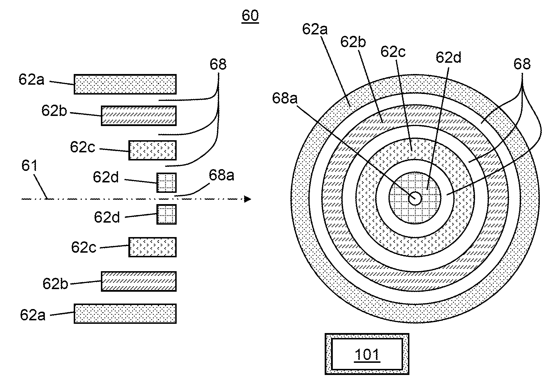
[0040]FIGS. 4A-4B provide schematic illustrations of a first ion transport apparatus in accordance with the present teachings. The ion transport apparatus 60 illustrated in FIG. 4A comprises a plurality of nested coaxially disposed tubular ...


PUM


Abstract

A method for transporting ions within a mass spectrometer comprises: inputting the ions and neutral molecules to a first end of an ion transport apparatus comprising a plurality of non co-planar ring-shaped electrode portions having respective central apertures having centers that lie along a common axis and that define an ion channel, the radii of the central apertures decreasing in a direction from the first end to a second end of the ion transport apparatus; applying a set of Radio Frequency voltages to the plurality of electrode portions such that the ions remain substantially confined to the ion channel while passing from the first to the second end; and exhausting the neutral molecules from the ion transport apparatus though a plurality of channels or apertures other than the apertures that define the ion channel, the exhausting performed in one or more directions that are non-perpendicular to the axis.

Description

FIELD OF THE INVENTION[0001]The present invention relates generally to ion optics for mass spectrometers, and more particularly to a device for transferring ions from one or more atmospheric-pressure or near-atmospheric-pressure ion source to an evacuated region.BACKGROUND OF THE INVENTION[0002]Mass spectrometry analysis techniques are generally carried out under conditions of high vacuum. However, various types of ion sources used to generate ions for MS analyses operate at or near atmospheric pressures. Thus, those skilled in the art are continually confronted with challenges associated with transporting ions and other charged particles generated at atmospheric or near atmospheric pressures, and in many cases contained within a large gas flow, into regions maintained under high vacuum.[0003]Various approaches have been proposed in the mass spectrometry art for improving ion transport efficiency into low vacuum regions. For example, FIGS. 1A-1B are two schematic depictions of mass ...

Claims


Application Information

Patent Timeline
Patent Type & Authority Patents(United States)
IPC IPC(8): H01J49/00H01J49/36H01J49/26
CPCH01J49/36H01J49/0027H01J49/066
Inventor WOUTERS, ELOY R.ATHERTON, R. PAULPRASAD, SATENDRADUNYACH, JEAN-JACQUES
Owner THERMO FINNIGAN
Why Eureka
Try Eureka