
Endoscopic vision system

a vision system and endoscope technology, applied in the field of endoscopes or optical large-angle endoscope systems, can solve the problems of monocular vision with limited depth perception, most depth of vision cues to be lost, and endoscopic surgery is technically more demanding than monocular vision

Inactive Publication Date: 2014-12-16
KATHOLIEKE UNIV LEUVEN
View PDF40 Cites 27 Cited by
  • Summary
  • Abstract
  • Description
  • Claims
  • Application Information

AI Technical Summary

Benefits of technology

This solution enhances surgical precision and safety by providing a wider field of view, reducing errors and operating time, and allowing for accurate 3D visualization and instrument positioning, even in deformable environments, without the need for additional incisions or complex stereo systems.

Problems solved by technology

Endoscopic surgery, however, is technically more demanding than ‘classical open surgery’ for several reasons such as smaller instruments, and the limitation of the smaller entry ports.
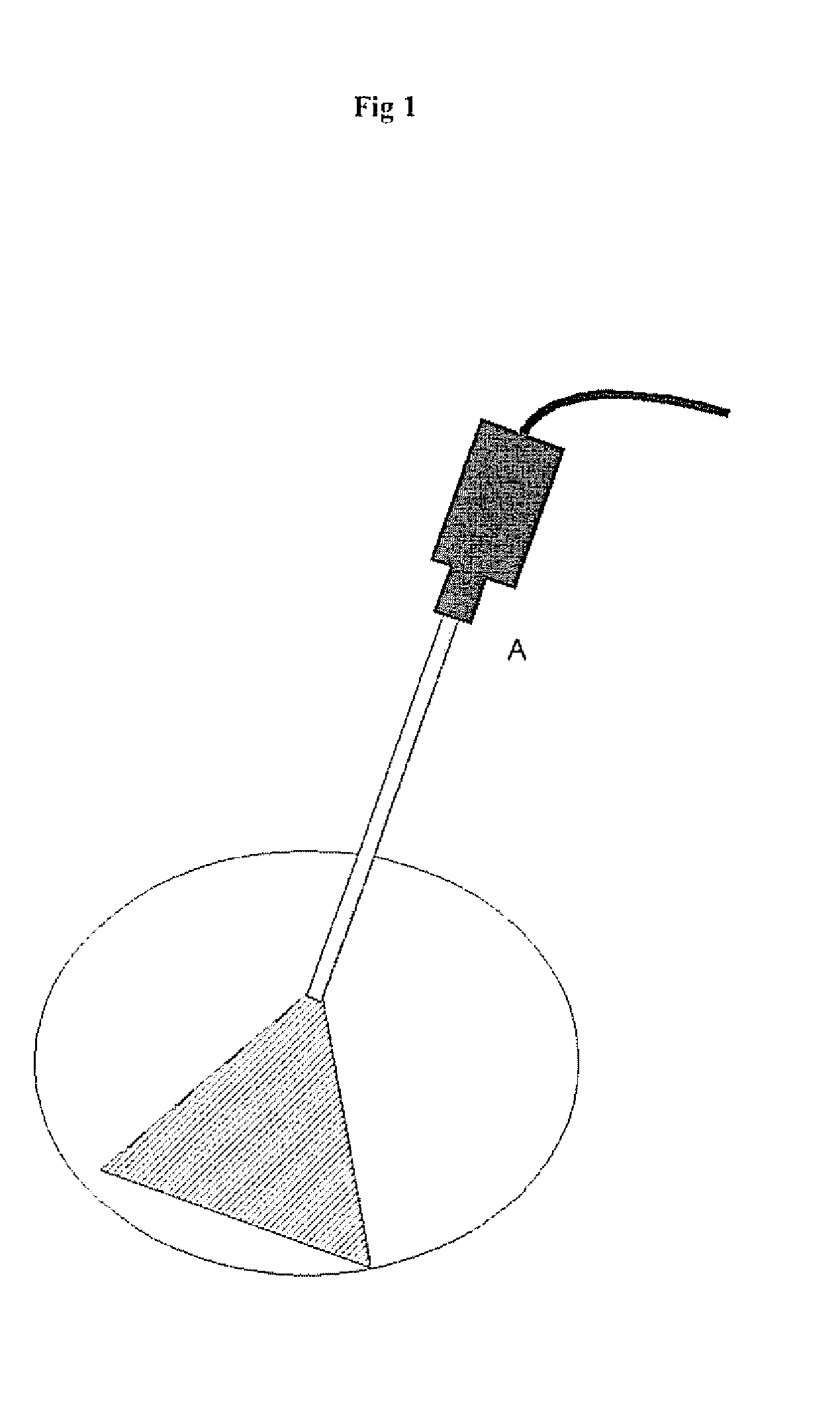
A crucial problem remains the monocular vision with limited depth perception, together with a small field of view also referred to as ‘tunnel vision’.
This causes most depth of vision cues to be lost.
The small field of view leads to difficulties of orientation and surgical mistakes.
Unexperienced surgeons perceive this problem much more since they are not able to mentally reconstruct such an overview of the working field.
Another limitation of the small field of view is the difficulty to position instruments into the field of view: surgery is performed with the lens at a short distance of the target tissue, eg 2 to 3 cm in order to obtain a sharp enlarged image.
It is obvious, that this requires time, slowing down the surgery.
If this fails, the operating field is flooded with blood, making things more difficult.
However, this approach has several drawbacks, like ego the need for an endoscope with a larger cross section or with smaller optical pathways.
Moreover, stereoscopic visualization has no transparent implementation yet and requires eg shutter glasses, auto-stereoscopic displays or head mounted displays.
Today these approaches to 3D visualization have failed to become widely accepted in endoscopic surgery because too cumbersome and too expensive without real demonstrable benefits.
These have the drawback, however, that a close up view can only be obtained with the lens at a short distance from the tissue, thus making the working distance, i.e. the distance between lens and tissue limited.
However, zooming and refocusing is not straightforward per-operatively and is no real option to get a quick overview of the scene.
Indeed if one hand holds a camera with a lens, a second hand is needed to adjust the angle of view; this second hand thus is no longer available for surgery.
A zoomed out camera view—even if used with larger monitors—is not practical to work with.
The former solution limits the working space, the latter solution makes an overview picture practically impossible.
Today lenses and camera units with a variable field of view exist but are not really used for practical reasons.

Method used


Image

  • Endoscopic vision system
  • Endoscopic vision system
  • Endoscopic vision system

Examples


example 1

Multiview Endoscopic Visualisation with Fine Tuning of the Multi View Camera Network

Embodiment of the Invention in Laparoscopy

[0053]In laparoscopy, being endoscopy in the abdominal cavity, endoscopes are normally rigid with a camera outside the body. The endoscope is inserted through a single small incision. Additional incisions allow to insert specific endoscopic (surgical) instruments. The working field contains considerably large variations in depth, relatively to the standoff (distance between tissue and lens) of the endoscopic telescopic lens. The telescope is used to visualize a particular region of interest within the abdominal cavity. This means that secondary regions are not visible to the surgeon or her / his staff. Nevertheless it often occurs that one or more assistants are keeping structures away outside the field of view. In such case this is done without any vision based feedback for neither the surgeon nor her / his assistants. The same reasoning applies when surgery is ...

example 2

Multiview Endoscopic Visualisation and Generation of a Synthetic Overview Image or Panorama

Implementation of the Optical Large View Endoscopic Systems of Present Invention

[0064]It is explained beforehand that scene interpretation and analysis—or the ‘intelligence’ offered by the endoscopic control unit—is what this apparatus really distinguishes from any other endoscopic imaging system.

[0065]On the one hand the apparatus can generate a regular endoscopic view, on the other hand the underlying scene model opens the way to a massive set of new technical / medical applications. The presentation of this enhanced information can be done transparently (ie a surgeon is presented subtly enriched information without s / he even realising it) or very explicitly. Examples of both will be provided as an illustration of the application domain. However an exhaustive description of the complete set of possible applications simply is not feasible. We hereunder as embodiments rather provide pointers to ...

first embodiment

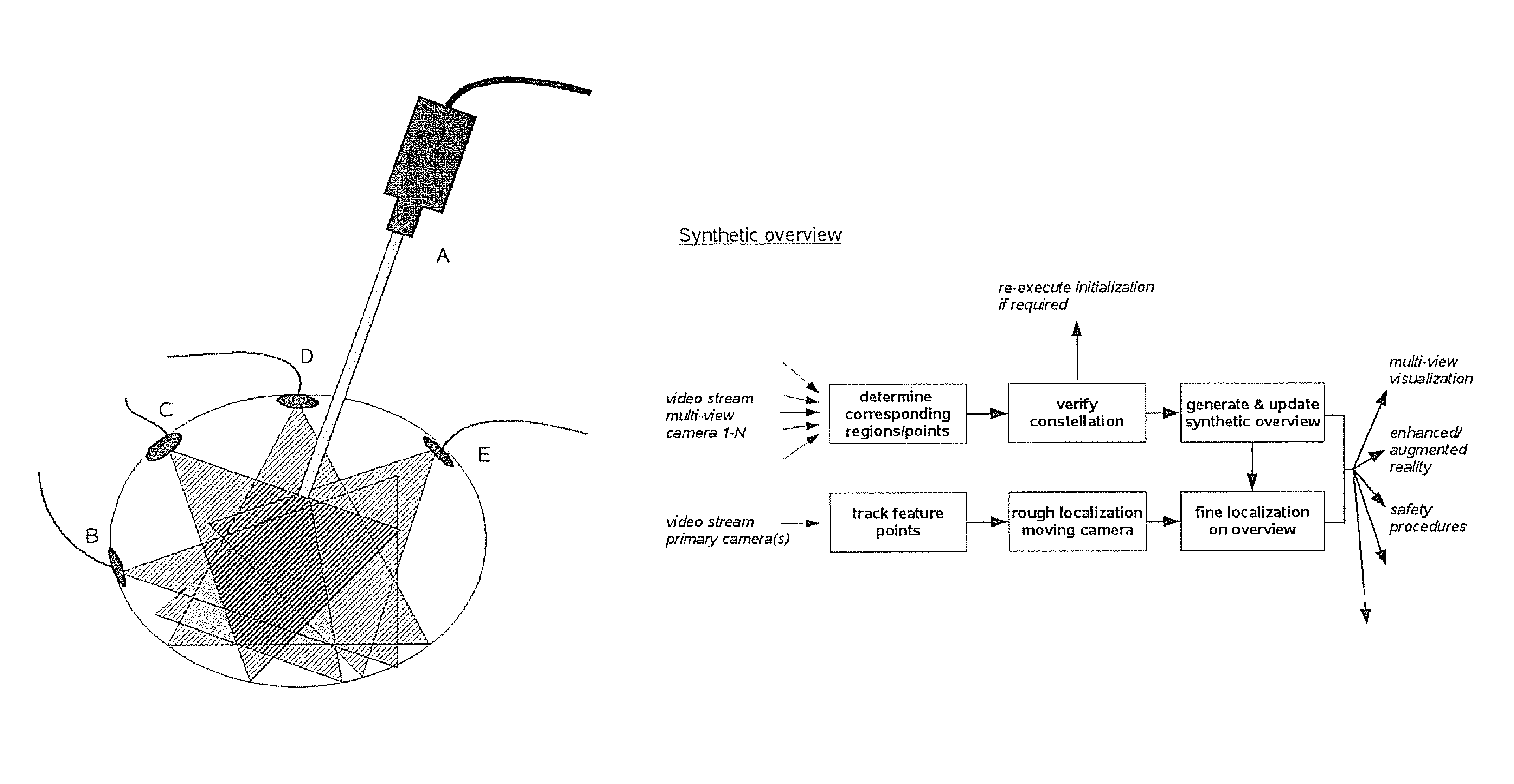
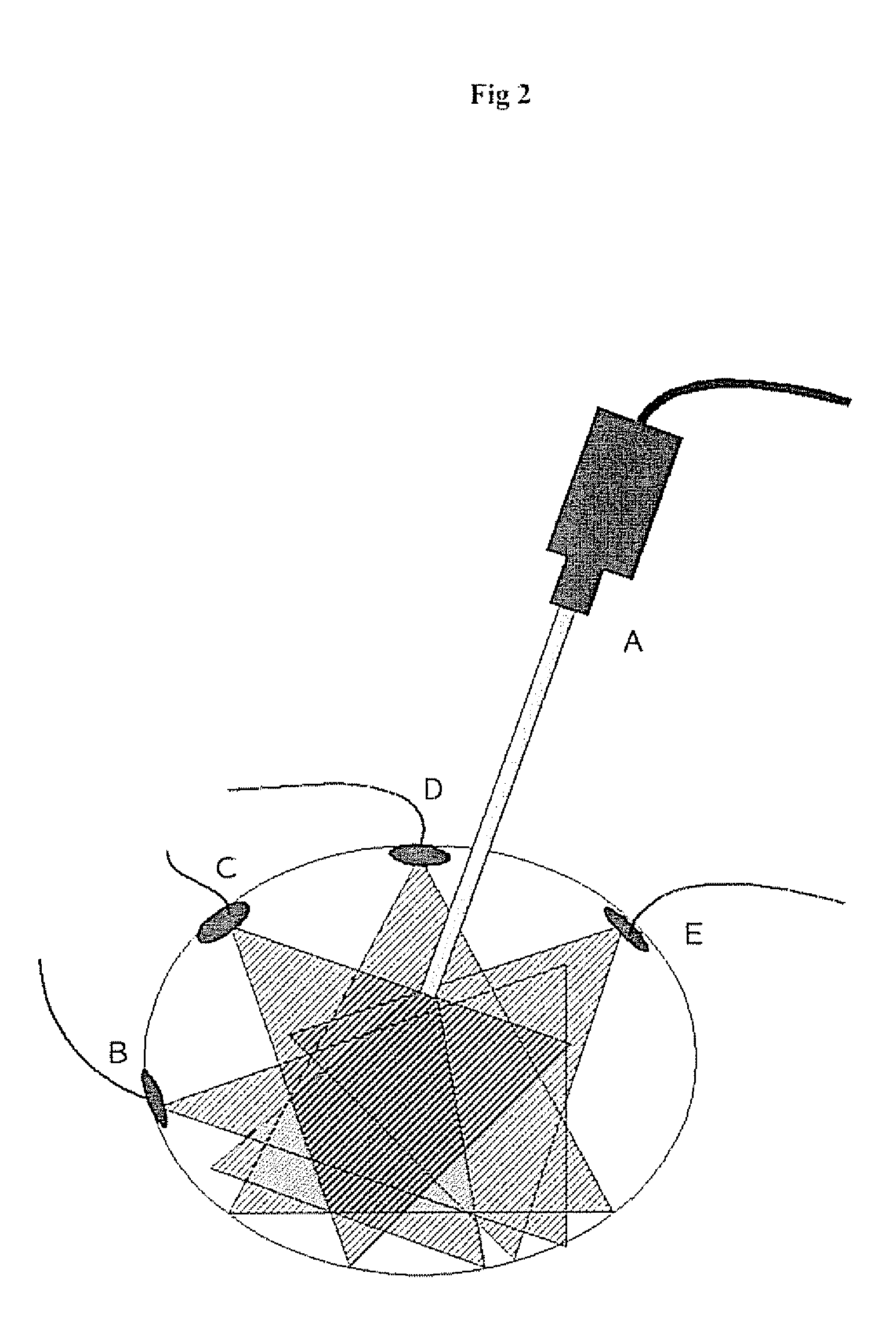
[0066]Integrating the different video feeds coming from the system described under ‘Example 1’ leads to a truly enlarged field of view, as a new virtual overview camera can be build. This virtual camera view interpolates smoothly between the real cameras and their real resolutions. This can not only make the new overview possibly an extremely wide angle, but also provides a movable viewpoint without the need for moving cameras. The same is true for adapted resolutions. The exact size of the wide angle is determined by the area of the scene coveted by the multi view cameras.

[0067]To this end a set of ‘secondary cameras’ (minimal two) is inserted, and attached so that the working field can be imaged (see also the description earlier). It is not a prerequisite for these cameras to be fully calibrated beforehand, but having a pre-calibration available increases robustness. Such a pre-calibration is performed using one of the standard techniques described in the literature (eg a “Tsai ca...


PUM


Abstract

A multiple viewpoint endoscope system having a multiple viewpoint camera setup and / or an intelligent or cognitive image control system and display device particularly adapted for localizing internal structures within a cavity or an enclosing structure, such as an animal body, for instance the abdomen of an animal or human, or for localizing a real or synthetic image of such internal structures within an overview image or on an overview 3D model.

Description

BACKGROUND OF THE INVENTION[0001]A. Field of the Invention[0002]The present invention relates to a novel endoscope or an optical large view endoscopic system with improved depth perception. In particular, a multiple viewpoint endoscope system comprising a multiple viewpoint camera setup and / or an intelligent or cognitive image control system and display device particularly adapted for localising internal structures within a cavity or an enclosing structure, such as an animal body, for instance the abdomen of an animal or human, or for localising a real or synthetic image of such internal structures within an overview image or on an overview 3D model.[0003]B. Description of the Related Art[0004]Endoscopy refers to techniques used to inspect or to look into internal cavities or hollow structures. Endoscopy is used today for medical applications and for industrial applications such as for instance in the visual inspection of aircraft, diesel and automotive engines by so called borescop...

Claims


Application Information

Patent Timeline
Patent Type & Authority Patents(United States)
IPC IPC(8): A61B1/00A61B1/04
CPCA61B1/042A61B1/00193A61B1/00181H04N2005/2255A61B1/0005A61B1/00194H04N23/555
Inventor KONINCKX, PHILIPPEKONINCKX, THOMASVAN GOOL, LUC
Owner KATHOLIEKE UNIV LEUVEN
Learn More