Laser machining apparatus with switchable laser system and laser machining method

a laser system and laser machining technology, applied in metal working equipment, welding equipment, metal-working equipment, etc., can solve the problems of insufficient time of laser pulse action on workpieces, negative effect on cutting tools, and workpiece thermally affected zones, etc., to achieve high-quality machined workpieces.

Active Publication Date: 2014-12-23
FRITZ STUDER AG
View PDF17 Cites 48 Cited by
  • Summary
  • Abstract
  • Description
  • Claims
  • Application Information

AI Technical Summary

Benefits of technology

[0007]The invention provides a laser machining apparatus (10), as well as a method for machining a workpiece (11). A rotating cutting tool having a cutting edge (62) and a flank (64) is manufactured from the workpiece (11). The laser machining apparatus (10) works in two different operating modes. In the first operating mode, a first laser head (14) is used for machining the workpiece (11) at high advance speeds of the workpiece (11) relative to the first laser head (14). In doing so, the workpiece (11) is cut by laser melt cutting so as to display a rough desired contour. In the first operating mode, the duration of the laser pulses is in the nanosecond range. Subsequently, the laser machining apparatus (10) is operated in the second operating mode. In doing so, the laser pulses are generated with a pulse duration in the picosecond range, said laser pulses exhibiting a smaller mean power than those in the first operating mode. In the second operating mode, a second laser head (15) in the form of a scanner head is activated by means of an optical scanner system (56). This optical scanner system directs the laser pulses onto a two-dimensional pulse area (65) on the surface of the workpiece (11). Different from the first operating mode I, the material removal is accomplished by laser ablation in the second operating mode. The thermally influenced zone formed in the first operating mode due to the thermal action of the laser pulses on the workpiece (11) is at least partially removed again by laser ablation during the subsequent machining step, so that a high quality of the machined workpiece (11) is achieved.
[0010]Indeed, high machining speeds are achieved in the first operating mode; however, due to the thermal action of the laser on the workpiece, a thermally affected zone is produced on the workpiece, said zone having a negative effect on the properties of the cutting tool that is to be produced, for example. Therefore, in the second operating mode, the laser arrangement machines the workpiece by laser ablation. The material is converted into a plasma cloud by ultra-short laser pulses, in which case the duration of the action of the laser pulses is so minimal that no thermally affected zone will form. In this case, the duration of action of the laser pulse on the workpiece is not adequate for this. During this second operating mode, preferably at least one part and, in particular, the entire thermally affected zone that has formed in the first operating mode is removed again. The thermally affected zone is removed at least in the regions of the workpiece where high quality is required such as, for example, in the regions of the cutting edge of a cutting tool. In both operating modes, the workpiece is machined at the same point of the outside contour in order to produce the desired three-dimensional form. Due to the two-step method, the workpiece mounted in the holding means can be machined very economically. In this manner, it is possible to thus manufacture cutting tools in a particularly efficient manner. In addition, high-quality workpiece machining is ensured.
[0012]It is advantageous when the first focus region in which the laser pulses emitted by the first laser head can be focused, does not have spatial intersections with the second focus region in which the laser pulses emitted by the second laser head can be focused. In particular, the first focus region of the first laser head is arranged along its optical axis at a first working distance from the first laser head. The second focus region is located at a second working distance from the second laser head. In a preferred embodiment, the second working distance is greater than the first working distance. This offers the advantage that, while the workpiece is being machined in the second operating mode, spatial moving and / or positioning of the workpiece relative to the second laser head are possible without impairment by the first laser head. As a rule, the finishing pass of the workpiece in the second operating mode requires a more complex alignment and movement of the workpiece relative to the second laser head with the use of the infeed axes than is the case in the first operating mode in the course of rough-cutting. If the second working distance is selected greater than the first working distance, a sufficiently large free space is available for tool movement.

Problems solved by technology

Indeed, high machining speeds are achieved in the first operating mode; however, due to the thermal action of the laser on the workpiece, a thermally affected zone is produced on the workpiece, said zone having a negative effect on the properties of the cutting tool that is to be produced, for example.
In this case, the duration of action of the laser pulse on the workpiece is not adequate for this.

Method used


Image

  • Laser machining apparatus with switchable laser system and laser machining method
  • Laser machining apparatus with switchable laser system and laser machining method
  • Laser machining apparatus with switchable laser system and laser machining method

Examples


Embodiment Construction

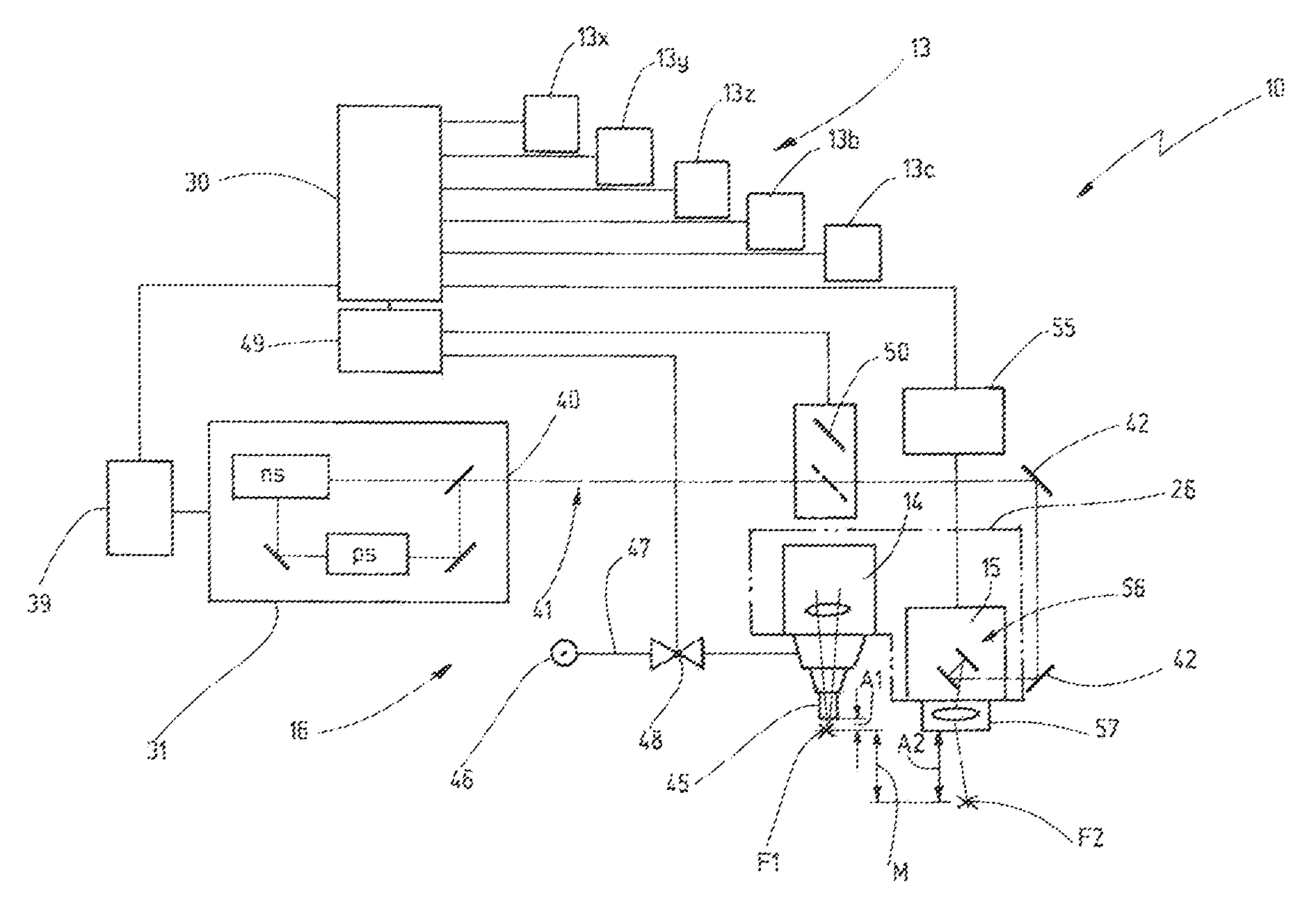
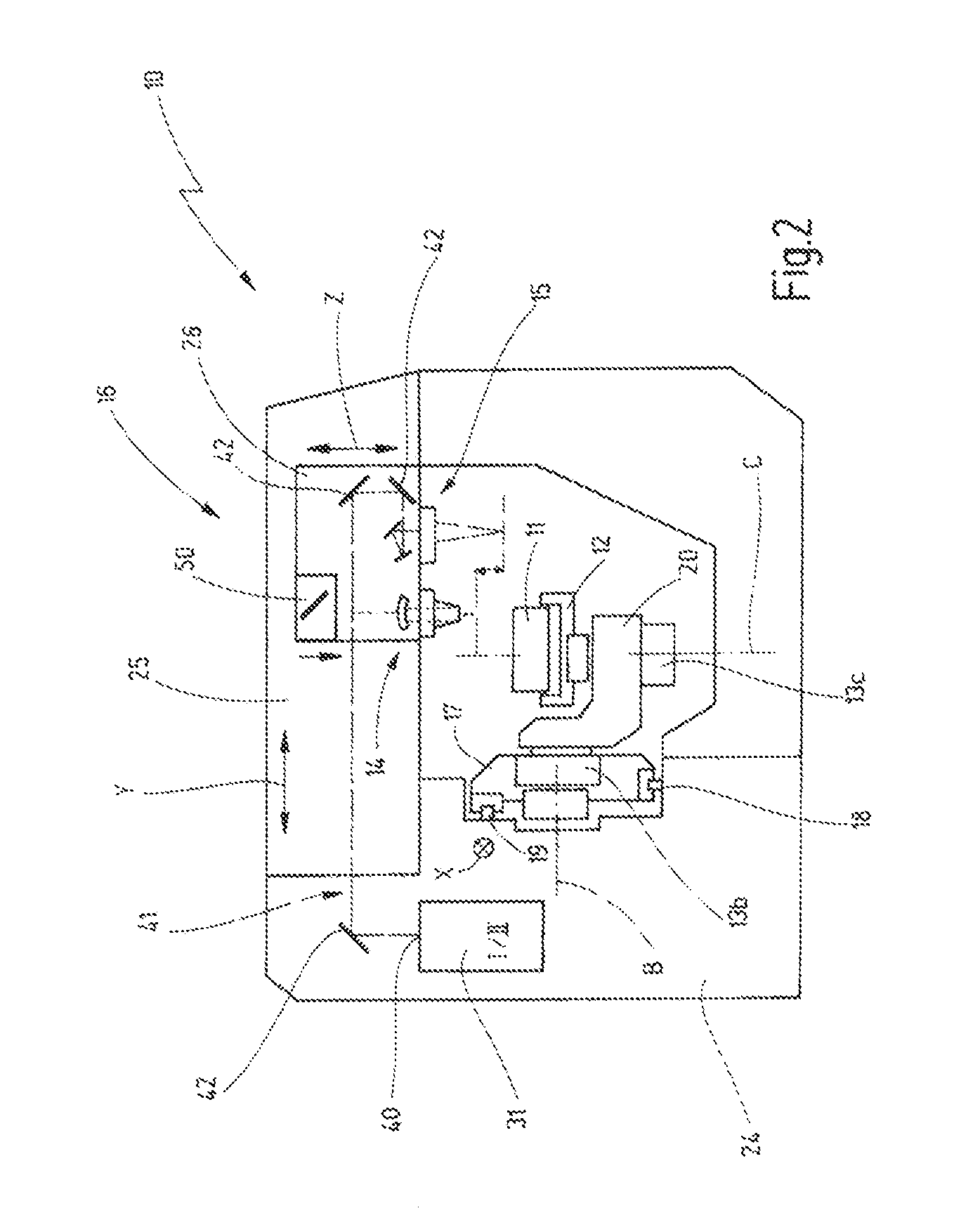
[0022]FIGS. 1 and 2 show an exemplary embodiment of a laser machining apparatus 10 for machining a workpiece 11 with laser pulses. The laser machining apparatus 10 comprises a holder 12 for holding or mounting the workpiece 11. In accordance with the exemplary embodiment it is possible, via five infeed axes 13, to move and / or position the holding means 12 or the workpiece 11 relative to a first laser head 14 and a second laser head 15 of a laser arrangement 16. The number of infeed axes 13 may also vary as a function of the desired machining of the workpiece 11. Up to six infeed axes 13 may be provided.

[0023]In the exemplary embodiment, some of the infeed axes 13 are embodied as a linear guide and some as a circular guide. The first linear guide 13x comprises a carriage 17 that can be moved linearly in X-direction, said carriage—in the exemplary embodiment—being supported from the top on a first rail 18 and being supported on said rail, as well as on a second rail 19 parallel theret...


PUM

PropertyMeasurementUnit
poweraaaaaaaaaa
poweraaaaaaaaaa
poweraaaaaaaaaa

Abstract

A laser machining apparatus and method for producing from a workpiece a rotating cutting tool having a cutting edge and a flank. The laser machining apparatus works in two different operating modes. In the first operating mode, a first laser head is used for machining the workpiece at high advance speeds of the workpiece relative to the first laser head to form a rough desired contour with pulses having a duration in the nanosecond range resulting in laser melt cutting. Subsequently, the laser machining apparatus is operated in the second operating mode generating laser pulses with having a pulse duration in the picosecond range. In the second operating mode, a second laser head is activated by means of an optical scanner system and directs the laser pulses onto a two-dimensional pulse area on the surface of the workpiece, the material removal is accomplished by laser ablation.

Description

CROSS-REFERENCE TO RELATED APPLICATION[0001]This application claims the priority of German Application No. 10 2011 000 768.7-34 filed Feb. 16, 2011.BACKGROUND OF THE INVENTION[0002]The invention relates to a laser machining apparatus for machining a workpiece with a laser, as well as to a laser machining method. The workpiece is a semi-finished product, for example, from which a cutting die or a rotating cutting tool having a cutting edge, a face and a flank is to be produced.[0003]Apparatus and methods for machining workpieces by laser have been known per se. For example, publication DE 100 20 559 A1 describes an apparatus for machining a material by using ultra-short laser pulses. In this case, the laser pulses have a pulse duration of less than 300 picoseconds. Furthermore, the apparatus comprises a testing device that is disposed to apply first laser pulses to the material or the workpiece, then to detect the results of this application, and to obtain information regarding the w...

Claims


Application Information

Patent Timeline
Patent Type & Authority Patents(United States)
IPC IPC(8): B23P25/00B23K26/38B23K26/36B23K26/08B23K26/42B23K26/06B23K26/30
CPCB23K26/42B23K26/36B23K26/0853B23K26/0635B23K26/083B23K26/38B23K26/0861B23P25/006B23K26/0884B23K26/365B23K26/70B23K26/0624B23K26/361
Inventor PLUSS, CHRISTOPH
Owner FRITZ STUDER AG
Why Eureka
Try Eureka