Precision transfer equipment
a technology of transfer equipment and bellows, which is applied in the direction of gearing, mechanical control devices, instruments, etc., can solve the problems that the bellows affect the accuracy of the bellows is not sufficiently achieved in the practical use, and the accuracy of the bellows is impaired, so as to achieve high accuracy, high precision movement, and high precision of position detection.
- Summary
- Abstract
- Description
- Claims
- Application Information
AI Technical Summary
Benefits of technology
Problems solved by technology
Method used
Image
Examples
first exemplary embodiment
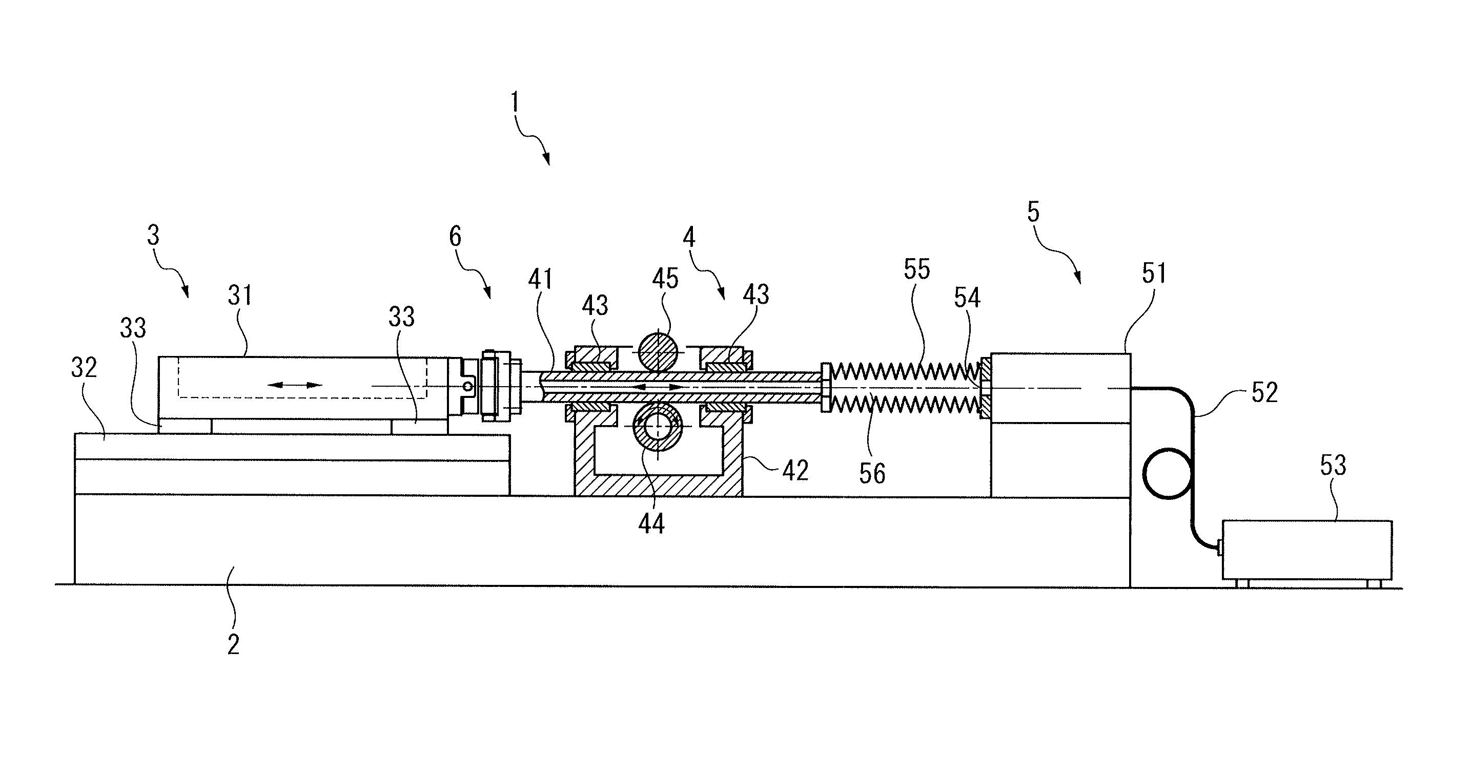
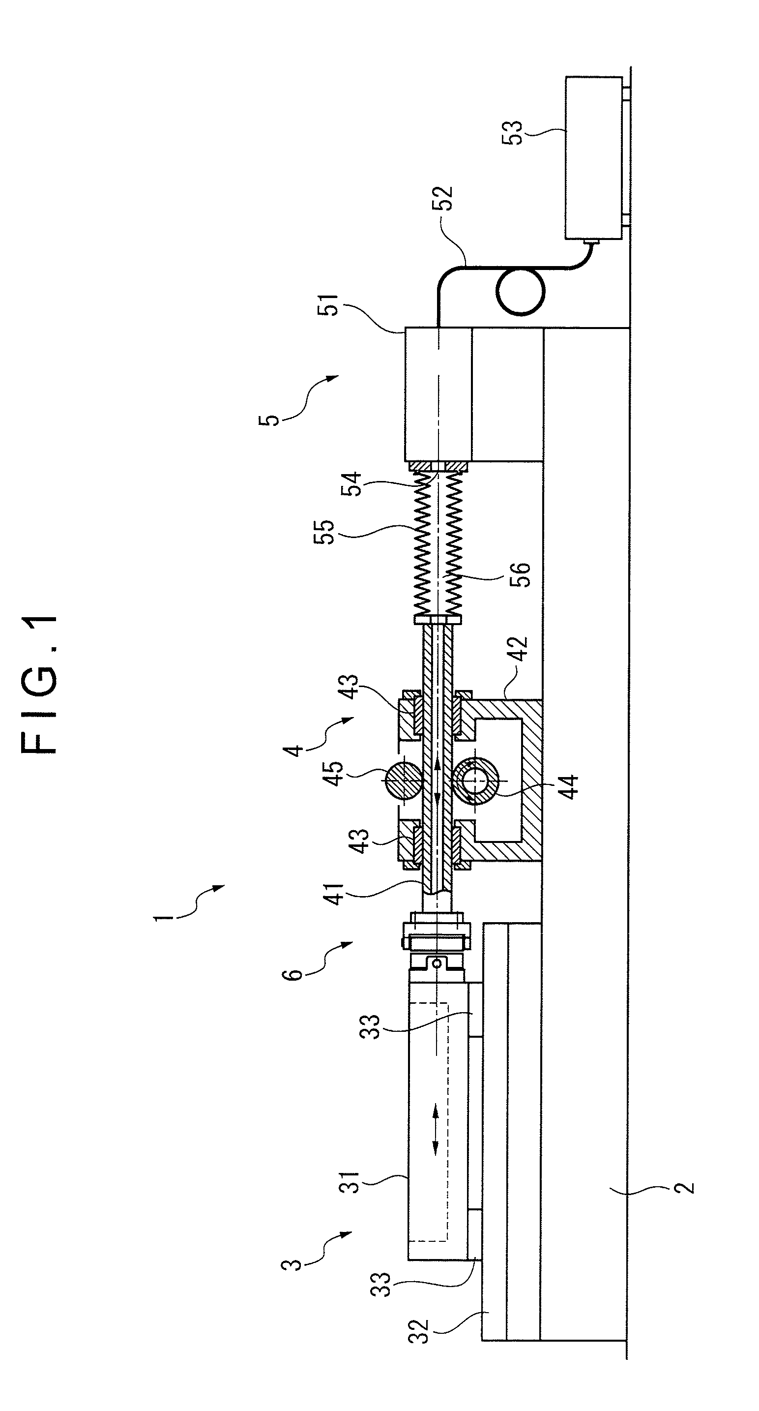
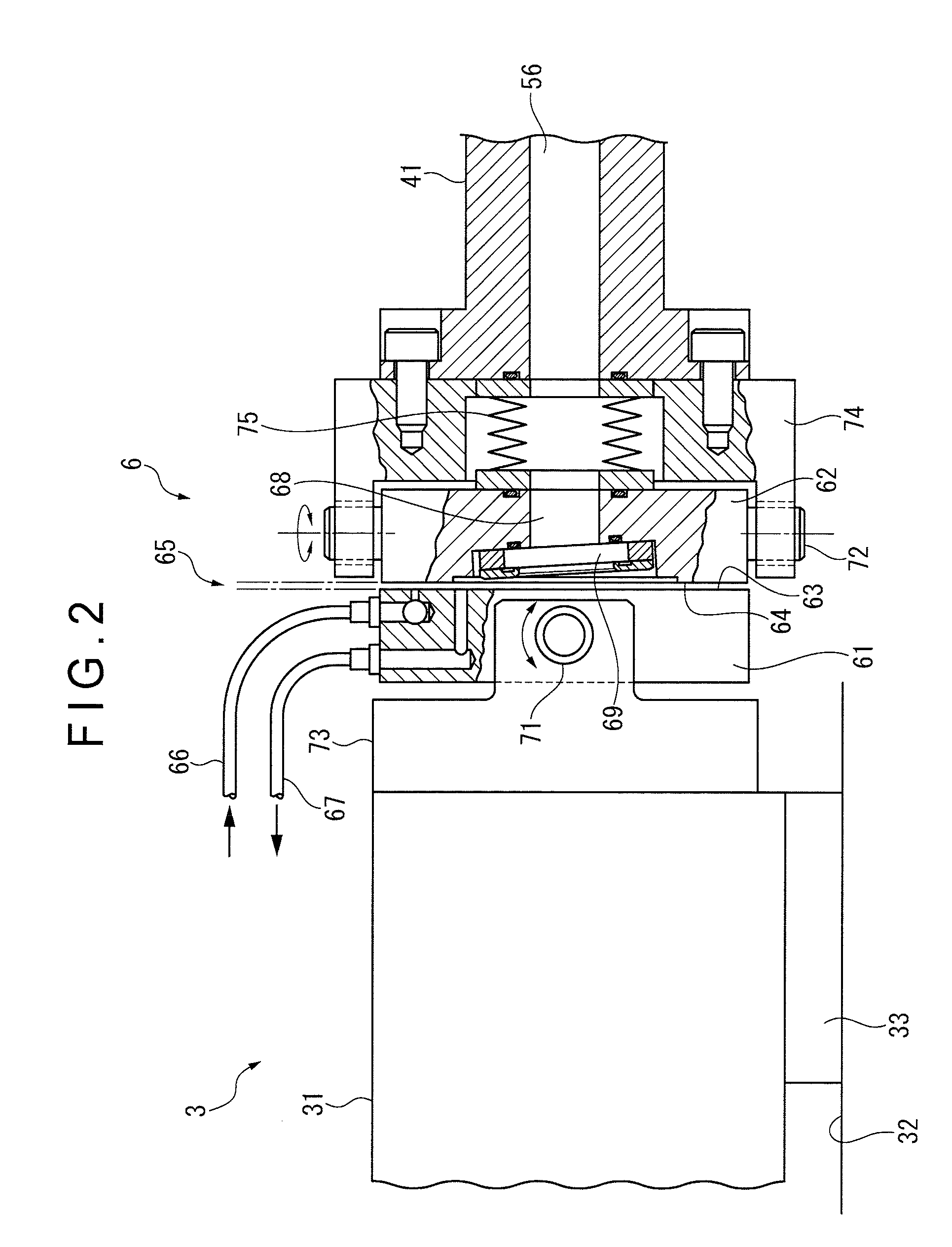
[0034]FIGS. 1 and 2 show the first exemplary embodiment of the invention.
[0035]In FIG. 1, precision transfer equipment 1 according to the first exemplary embodiment includes: a base 2; and a table mechanism 3, a drive mechanism 4 and a laser interferometer 5 provided on the base 2.
[0036]The base 2 is fixed on a stable foundation while an upper surface of the base 2 is formed horizontal.
[0037]The table mechanism 3 supports a table 31 (a movable body) and includes a guide rail 32 that is fixed on the base 2.
[0038]A guide bearing 33 is provided on a bottom surface of the table 31. The table 31 is supported by the base 2 through the guide bearing 33 and the guide rail 32.
[0039]The guide rail 32 is continuously formed in a predetermined moving direction (in a predetermined direction for moving the table 31) while an upper surface of the guide rail 32 is made horizontal, flat and smooth.
[0040]The guide bearing 33 is a static-pressure air bearing that forms a static-pressure clearance betw...
second exemplary embodiment
[0076]FIG. 3 shows a second exemplary embodiment of the invention.
[0077]In FIG. 3, precision transfer equipment 1A according to the second exemplary embodiment includes: the base 2; and the table mechanism 3, the drive mechanism 4 and the laser interferometer 5 provided on the base 2.
[0078]The above components other than the drive mechanism 4 are the same as those in the precision transfer equipment 1 according to the first exemplary embodiment and are given with the same reference numerals in which overlapping description of the components will be omitted.
[0079]The drive mechanism 4 includes the casing 42, the rod guide 43 and the drive roller 44 in order to drive the rod 41. Herein, the rod 41, the casing 42 and the rod guide 43 are the same as those in the precision transfer equipment 1 according to the first exemplary embodiment and are given with the same reference numerals in which overlapping description of the components will be omitted.
[0080]The drive mechanism 4 is differe...
third exemplary embodiment
[0083]FIG. 4 shows a third exemplary embodiment of the invention.
[0084]Precision transfer equipment according to the third exemplary embodiment is basically the same as the above-described precision transfer equipment 1 according to the first exemplary embodiment, in which only the joint 6 is different. Accordingly, the same components as those in the precision transfer equipment 1 according to the first exemplary embodiment are given with the same reference numerals in which overlapping description of the components will be omitted. The joint 6 having a different structure will be described below.
[0085]In FIG. 4, the joint 6 includes the movement member 61, the drive member 62, the movement surface 63, the drive surface 64, the static-pressure clearance 65, the fluid supply channel 66, the fluid discharge channel 67, the through hole 68 and the transparent plate 69 in the same manner as in the first exemplary embodiment.
[0086]However, the gimbal mechanisms for supporting the moveme...
PUM
| Property | Measurement | Unit |
|---|---|---|
| displacement | aaaaa | aaaaa |
| pressure | aaaaa | aaaaa |
| static-pressure | aaaaa | aaaaa |
Abstract
Description
Claims
Application Information
 - R&D
- Intellectual Property
- Life Sciences
- Materials
- Tech Scout
- Unparalleled Data Quality
- Higher Quality Content
- 60% Fewer Hallucinations
Browse by: Latest US Patents, China's latest patents, Technical Efficacy Thesaurus, Application Domain, Technology Topic, Popular Technical Reports.
© 2025 PatSnap. All rights reserved.Legal|Privacy policy|Modern Slavery Act Transparency Statement|Sitemap|About US| Contact US: help@patsnap.com


