Apparatus to deploy and expand web material

a technology of web material and apparatus, applied in the direction of thin material processing, transportation and packaging, filament handling, etc., can solve the problems of paper material being supplied in an unexpanded state, occupying far less space, and large and bulky devices, so as to achieve convenient use, reduce costs, and be more compact

Active Publication Date: 2014-12-30
KUCHARCO
View PDF35 Cites 15 Cited by
  • Summary
  • Abstract
  • Description
  • Claims
  • Application Information

AI Technical Summary

Benefits of technology

[0005]The Present Invention is an improved dispenser that is more compact, less expensive, and easier to use than the Original Dispenser. As with the Original Dispenser, the web material also has longitudinal strands on opposite sides. The device of the Present Invention tracks the threaded web material over three rollers instead of two and over a shorter distance than the Original Dispenser. The Present Invention uses an improved braking mechanism that creates web tension to pull the paper from the roll more effectively. After the web material is threaded through the mechanism, simply pulling the web material on the opposite side from the rollers deploys and expands it simultaneously. The unit can accommodate a plurality of rolls of web material mounted to deploy and expand either individually or simultaneously. The web material itself may have more than one layer. It is easier to create a motorized version for the dispenser of the Present Invention than for the Original Dispenser.

Problems solved by technology

However, the paper material can be supplied in an unexpanded state on a roll, and it occupies far less space than pre-expanded bubble wrap.
This device is large and bulky, and expansion is not as uniform as could be desired.

Method used


Image

  • Apparatus to deploy and expand web material
  • Apparatus to deploy and expand web material
  • Apparatus to deploy and expand web material

Examples


first embodiment

[0050]FIG. 6 is an isometric exploded view of the dispenser. The function of the top U-bolt 1 is to hold the axle 6 in place. Axle 6 is used to support a roll of unexpanded web material. Axle 6 is locked into position on the main support tube 5, which is secured to the base 14. It is held in place using pin 11 in conjunction with U-bolt 12, alignment plate 13 to stabilizing crossbar 16. It is fastened in place using washers 18 and locking nuts 19.

[0051]The U-bolt 1 is held in place on the top of the main support tube 5 using metal plate 2, washers 3, and nuts 4.

[0052]U-bolt 12 passes through alignment plate 13, through-holes 15 of base 14 and through-holes 17 of stabilizing crossbar 16.

[0053]Rubber feet 20 allow the unit to rest on a horizontal surface. There are three rubber feet, two of which are fastened to crossbar 16, and one that is fastened to base plate 14 using bolt 21.

[0054]Mounting plate 27 has three rectangular slots 28 having rounded corners for bolts to fasten guide wh...

second embodiment

[0077]FIG. 20 is an isometric exploded view of the dispenser shown in FIG. 19. Here, the upper axle is mounted to the top of the main support tube 5 using the U-Bolt first mounting embodiment, while the lower axle is mounted to an intermediate height position on tube 5 using bolt 40 with the second alternate side-mounting embodiment.

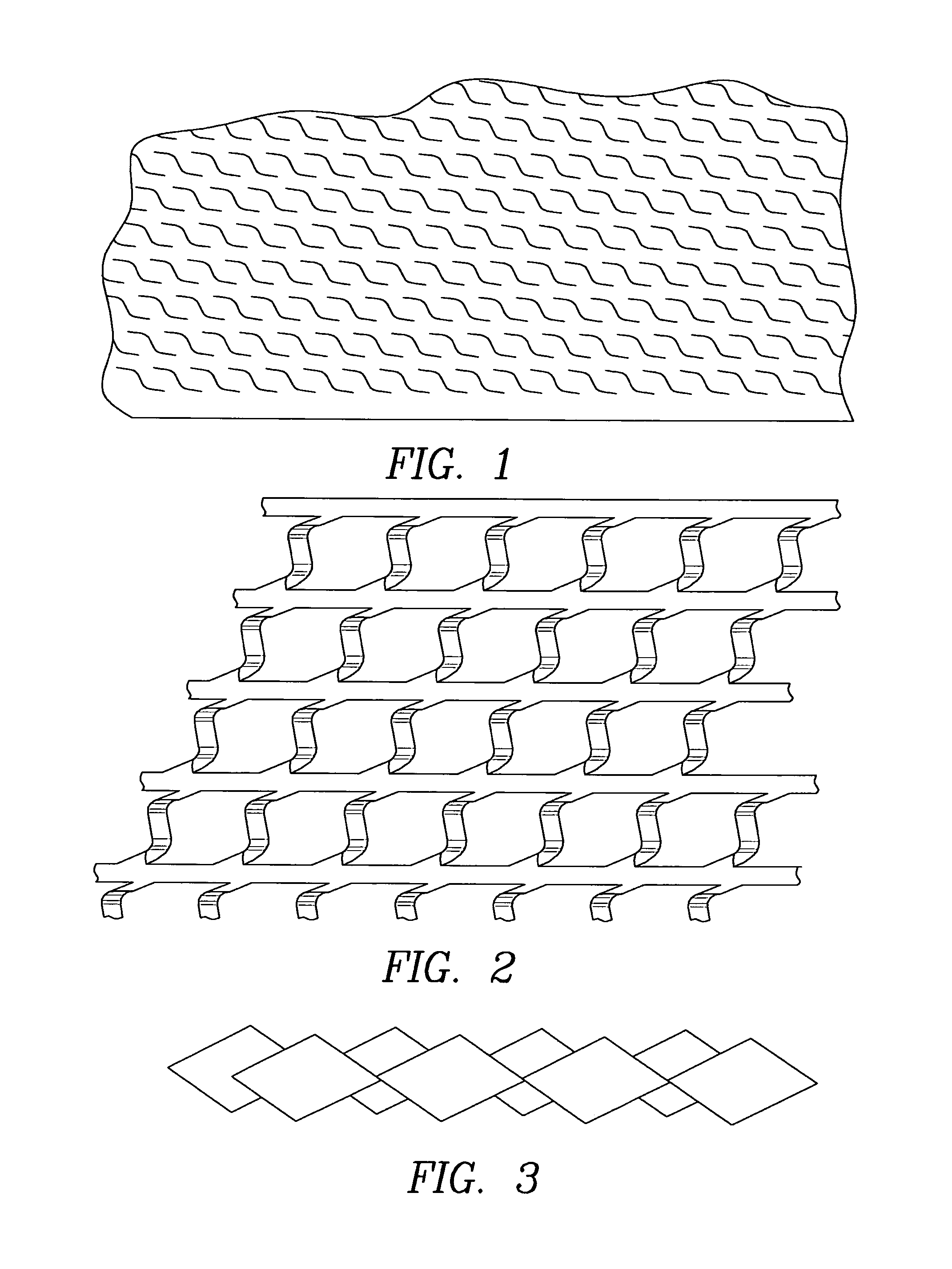
[0078]FIG. 21 shows the unexpanded web material wound around cardboard core 39. Two core plugs fit into both ends of the core. The axle passes through the center of both core plugs to facilitate mounting the web material.

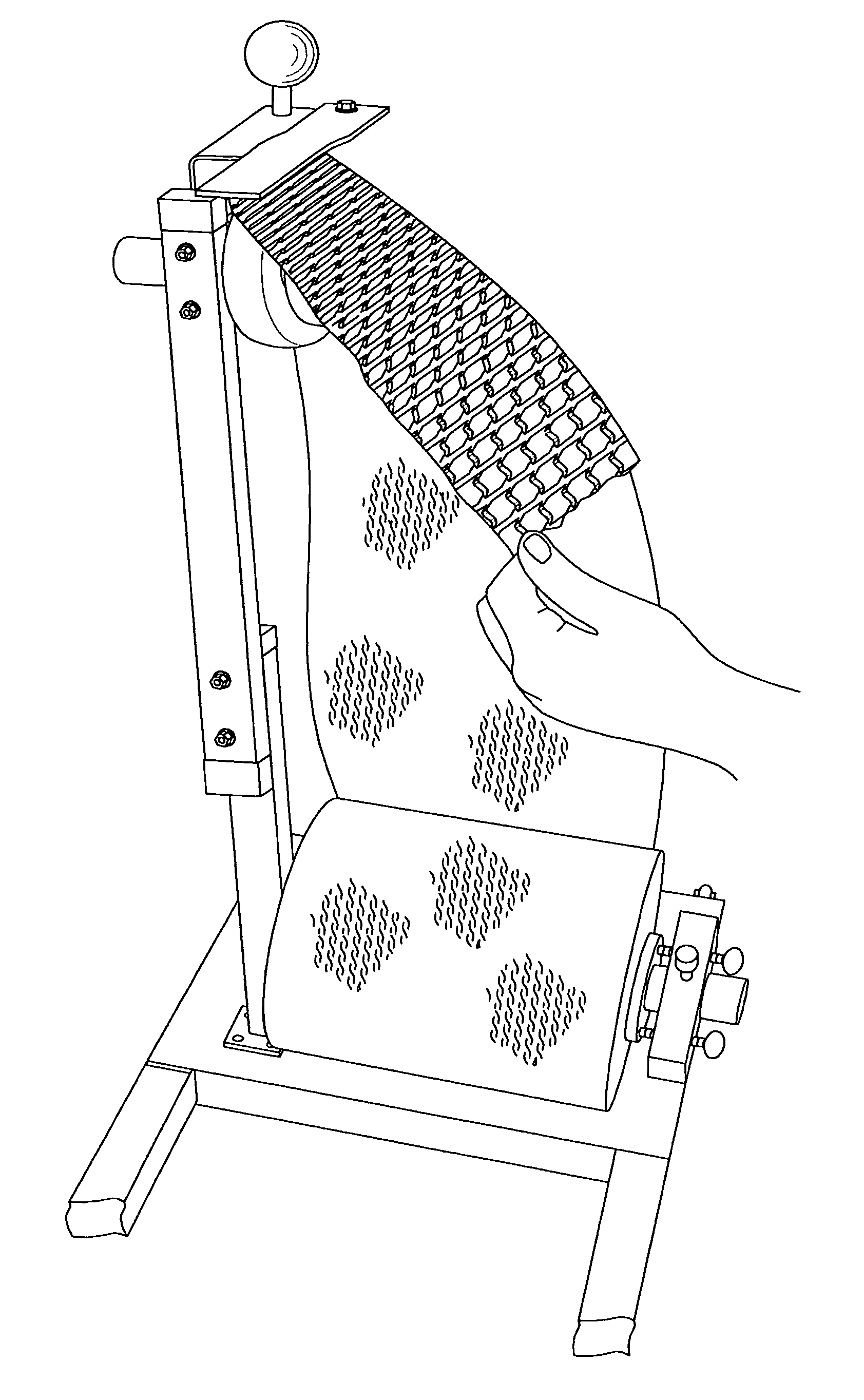
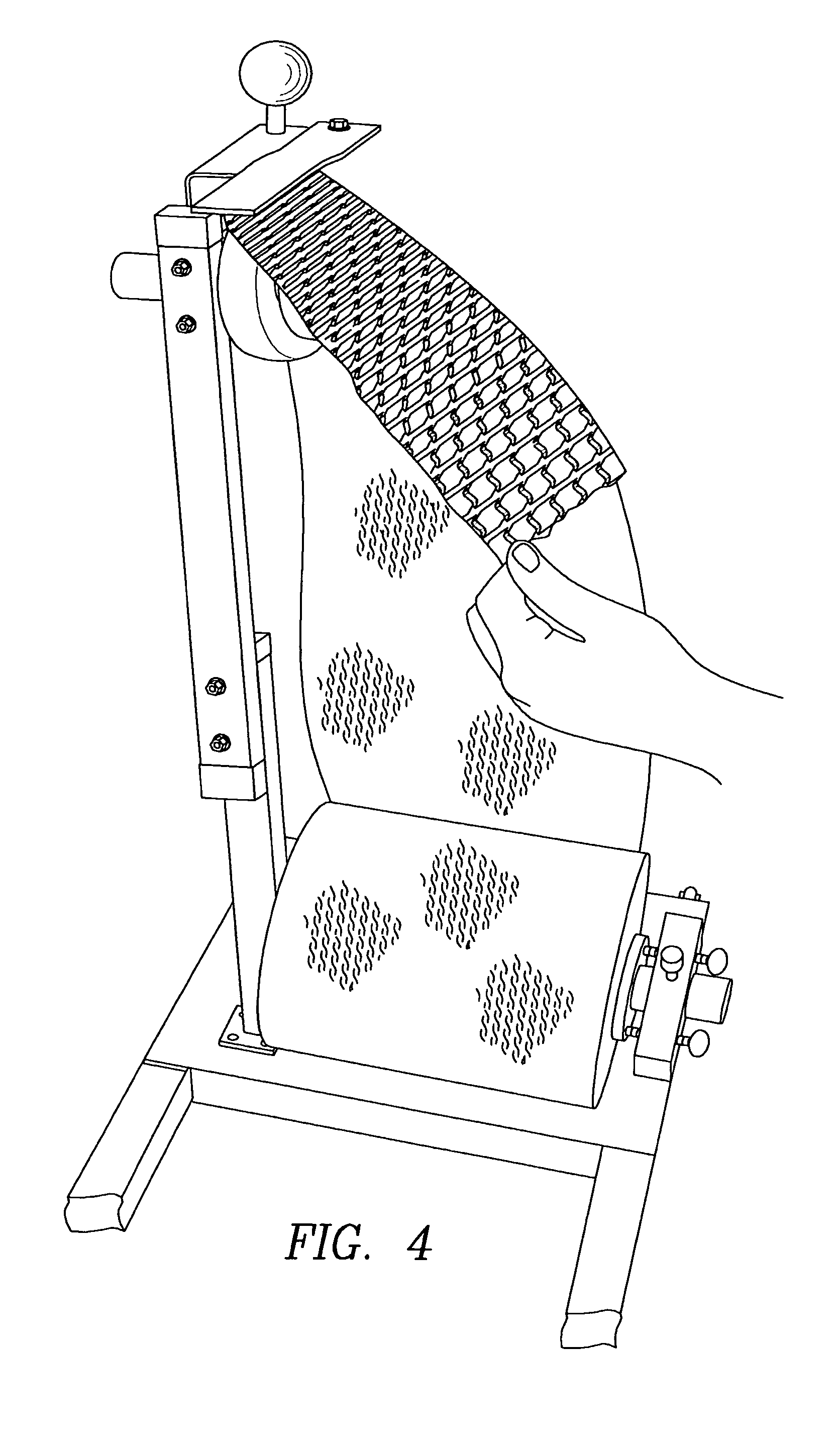
[0079]FIG. 22 is a schematic of a single roll of web material during deployment from a single axle dispenser. FIG. 23 is a schematic of two rolls of web material during deployment from a double axle dispenser. FIG. 24 is a schematic of three rolls of web material during deployment from a triple axle dispenser. FIG. 25 shows how two rolls of web material would be deployed with a double axle dispenser. The unexpanded web material from both...

third embodiment

[0082]FIGS. 31 and 32 show a single axle dispenser with a notch 47 cut in the base 14 (on the side opposite the stabilizing crossbar 16) to accommodate insertion of a motorized assembly. FIG. 31 shows one isometric view of this embodiment, while FIG. 32 is a reversed isometric view. The unit may be built in either orientation.

[0083]FIG. 33 is the first embodiment of the motorized dispenser. The stabilizing crossbar 48 of the motor assembly is inserted into notch 47 of base 14. The motor assembly comprises stabilizing crossbar 48, a support tube 49 for the motor assembly, a mounting plate 50 for the motor assembly, a main drive wheel 51, idler tracking wheels 52, motor 53, pinch roller 54, and switch 55. The web material itself comprises two strands running longitudinally on either side of the web. The unexpanded web material is threaded through both the guide wheel assembly and the motor assembly rollers. An exemplary configuration of the guide wheel assembly comprising guide wheels...


PUM

PropertyMeasurementUnit
flexibleaaaaaaaaaa
lengthaaaaaaaaaa
distanceaaaaaaaaaa

Abstract

A dispenser to deploy and expand cut web material uniformly to form a three dimensional lattice. The unexpanded web material is substantially longer than it is wide. The web material is die cut and has essentially parallel longitudinal strands on opposite transverse sides. The dispenser tracks the threaded web material over three rollers, and uses an adjustable braking mechanism that creates diagonal web tension to pull the paper from the roll. After the web material is threaded through the mechanism, simply pulling the web material on the opposite side from the rollers deploys and expands it simultaneously. The unit can accommodate a plurality of rolls of web material mounted to deploy and expand either individually or simultaneously. The web material itself may have more than one layer. An exemplary embodiment of the dispenser is a motorized version, where a motorized guide wheel assembly pulls the web material, thereby eliminating the necessity of manual deployment.

Description

CROSS REFERENCE TO RELATED APPLICATIONS[0001]This Present application is a continuation-in-part (CIP) of my currently pending U.S. patent application Ser. No. 12 / 943,822 filed on Nov. 10, 2010 entitled “APPARATUS TO DEPLOY AND EXPAND WEB MATERIAL” (hereinafter, the Parent application), which is in turn the non-provisional counterpart of U.S. Provisional Patent Application Ser. No. 61 / 260,807 filed on Nov. 12, 2009. The Present application claims the benefit of and priority to said Provisional patent application and the Parent application which are both incorporated herein by reference in their entirety. The Present application is also related to my U.S. Pat. No. 6,929,843, issued on Aug. 16, 2005, entitled Fence Tape, which is also incorporated by reference herein in its entirety. Said US patent is hereinafter referred to as the Fence Tape Patent. It is also related to my currently pending U.S. patent application Ser. No. 12 / 755,316 filed on Apr. 6, 2010 entitled “EXPANDABLE WEB MAT...

Claims


Application Information

Patent Timeline
Patent Type & Authority Patents(United States)
IPC IPC(8): B65H16/00B65H23/022B65H75/18
CPCB65H16/005B65H23/022B65H2301/41369
Inventor KUCHAR, MATTHEW J.KUCHAR, DAVID M.
Owner KUCHARCO
Why Eureka
Try Eureka