Heat exchanger pressure test shield

a technology of heat exchanger and pressure test, which is applied in the direction of heat exchange simulation, door/window protective devices, lighting and heating apparatus, etc., can solve the problems of unfavorable heat exchange, undesired fluid mixing, and insufficient shielding, so as to reduce the overall number of shields required

Inactive Publication Date: 2014-12-30
SNYDER KEITH W
View PDF1 Cites 0 Cited by
  • Summary
  • Abstract
  • Description
  • Claims
  • Application Information

AI Technical Summary

Benefits of technology

[0010]It is an object of this invention to provide a safe, transparent shield, which can be simply attached to the end flange of a shell and tube heat exchanger, and, can withstand the impact from a tube plug ejected from a tube under pressure.
[0011]It is another object of the invention to provide a shield that can be attached to a range of heat exchanger flange diameters, reducing the overall number of total shields required at a single facility.

Problems solved by technology

The tubes in a Shell-and-Tube heat exchanger can corrode over time, allowing for the undesired mixing of fluids.
This practice is unsafe, as these materials do not provide adequate protection in case of plug ejection.
Without a standard, and proven safe shield, workers must rig some temporary shielding, including but not limited to the above mentioned materials, which can prove to be time consuming and inadequately supported.
And, since the heat exchangers are usually used outdoors in a large industrial facility, they are not always easy to access for rigged temporary shielding, as they may be located in stacks extending high off the ground, with limited accessibility.
This system is limited to rectangular shielding and cannot be attached to the end of a heat exchanger efficiently.
There has been limited testing, with most tests occurring in the ballistic range of velocities of 1000-3000 ft / s.
In addition, it should stop the tube plug with minimal movement, as the observer will be looking through the shield, and a large deflection could cause the shield material itself to hit the observer.

Method used


Image

  • Heat exchanger pressure test shield
  • Heat exchanger pressure test shield
  • Heat exchanger pressure test shield

Examples


Embodiment Construction

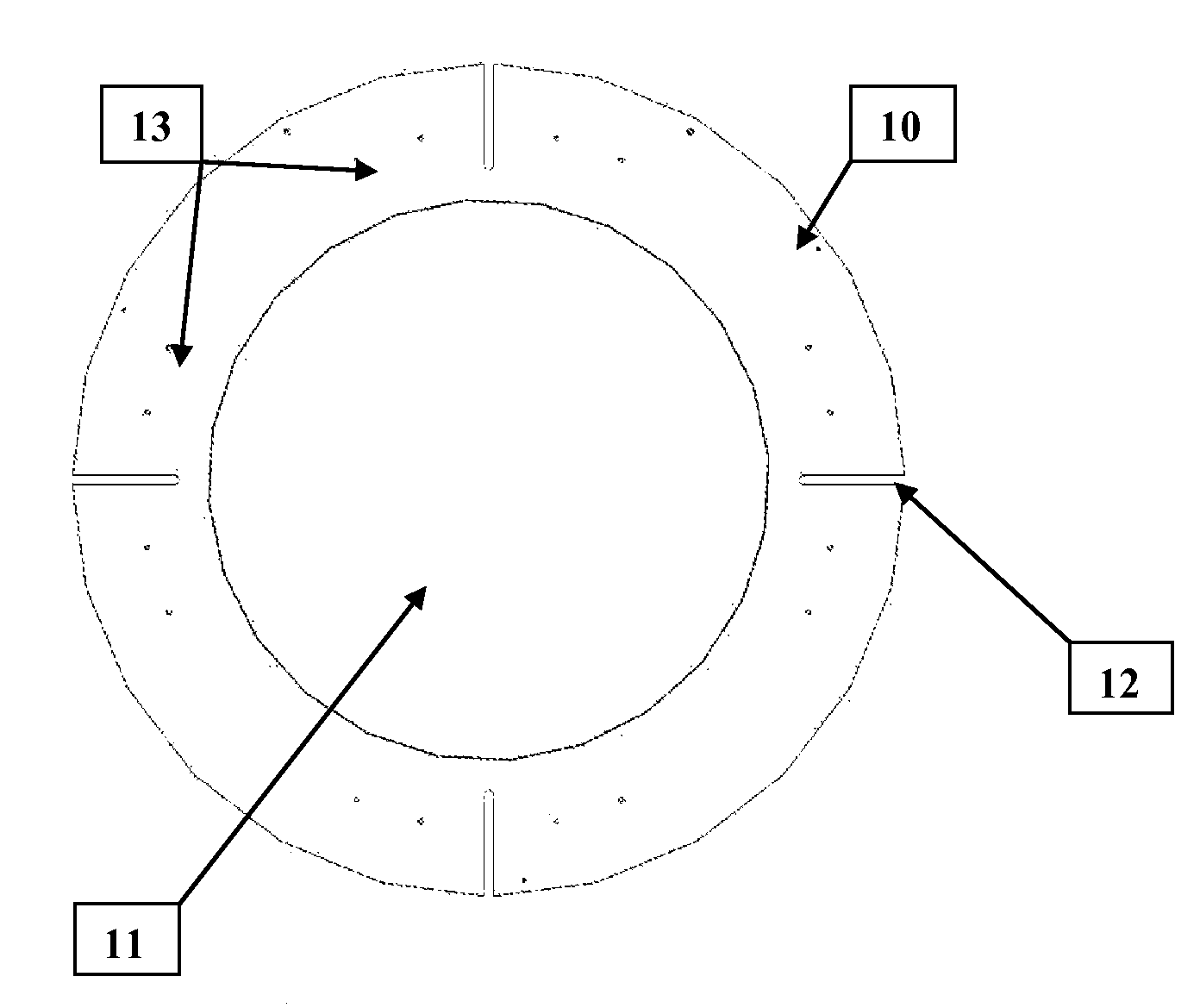
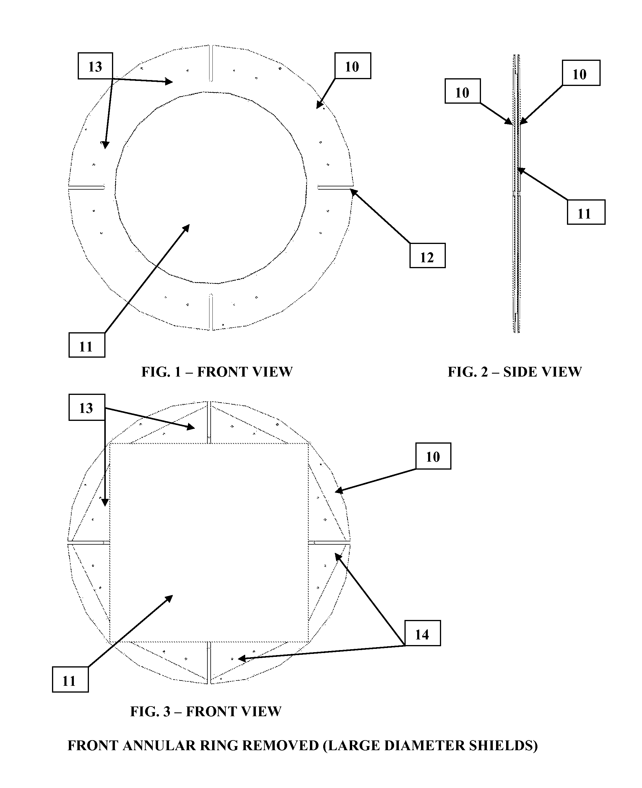
[0017]In accordance with the best mode of this invention, FIG. 1 shows a front view of the assembled heat exchanger pressure test shield which includes the polycarbonate shielding material 11, clamped between a rear and front annular metal ring 10. The clamping means is obtained through the use of through flat head bolts, countersunk on the rear annular ring, passing through the assembly at spaced locations 13, and secured with locknuts on the front annular ring. The assembled heat exchanger pressure test shield is then attached to the heat exchanger undergoing pressure testing by removing the channel cover on the heat exchanger, then replacing with the shield and mounting with (4)—¾″ diameter studs to the heat exchanger channel cover flange at slot locations 12.

[0018]FIG. 2 is a side view of the heat exchanger pressure test shield, illustrating the front and rear metal annular rings 10, and the polycarbonate shielding material 11 clamped between.

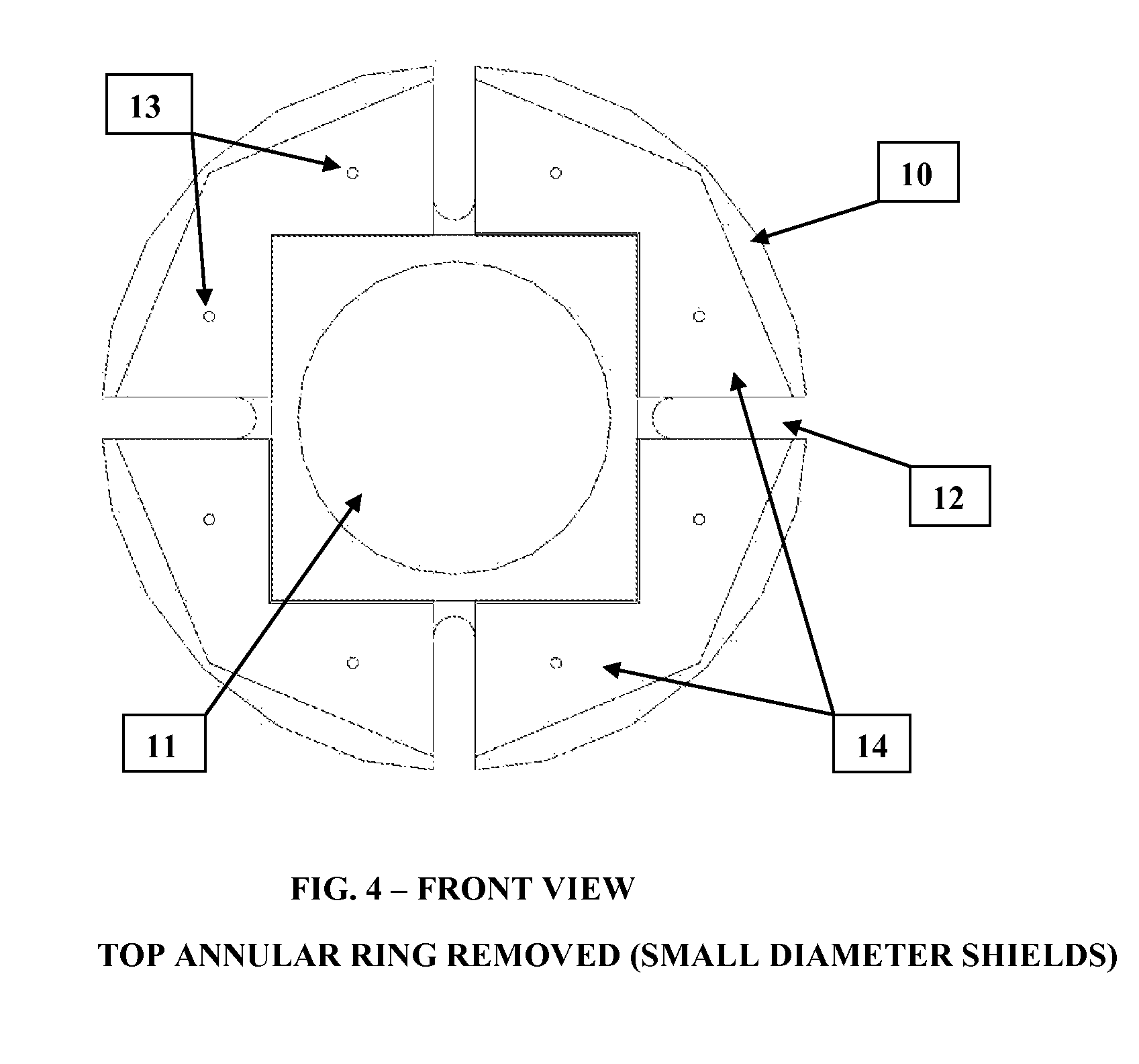
[0019]FIGS. 3 and 4 show the front v...


PUM


Abstract

Disclosed is a heat exchanger pressure test shield to protect observers from a shell and tube heat exchanger plug ejection during a hydrostatic pressure test. The shield provides a transparent high impact resistant shield material clamped between two annular rings. This shield material is isolated from the annular rings by a flexible gasket, which allows slight movement of the shield material upon impact, which is necessary to prevent failure. The heat exchanger pressure test shield is mounted to the channel cover flange, after removal of the channel cover, with several studs passing through an adjustable slot, enabling attachment to a range of heat exchanger diameter sizes. The heat exchanger pressure test shield, with adjustable slot attachment, enables visual inspection of tube plugs during pressure testing at a lower cost, while significantly improving the safety of the observer.

Description

BACKGROUND OF THE INVENTION[0001]1. Field of the Invention[0002]The present invention relates to shielding workers from a tube plug ejection, during hydrostatic pressure testing of shell-and-tube heat exchangers. It replaces the channel cover during testing to allow observance of tube plugs to check for leakage.[0003]2. Description of the Prior Art[0004]The tubes in a Shell-and-Tube heat exchanger can corrode over time, allowing for the undesired mixing of fluids. When a tube corrodes enough to fail, the tube is plugged with a tapered metal plug, commonly referred to as a tube plug. These tube plugs are inserted into both ends of the tube at the tubesheet, which eliminates the use of that tube, but allows continued operation of the heat exchanger without the mixing of fluids. Following tube plugging, a hydrotest, or hydrostatic pressure test, of the exchanger shell side is usually conducted with the channel cover removed so that leaks can be detected on the tube side face of the sta...

Claims


Application Information

Patent Timeline
Patent Type & Authority Patents(United States)
IPC IPC(8): F28F7/00
CPCF28F7/00F28F27/00E04H9/10F28F11/02F28F2200/00F28F2265/00F28F2265/02Y10T428/21Y10T428/218
Inventor SNYDER, KEITH, W.
Owner SNYDER KEITH W
Why Eureka
Try Eureka