Steering control system for hydrostatically driven front vehicle ground wheels and steerable rear caster wheels

a steering control system and hydrostatic drive technology, which is applied in the direction of steering linkages, non-deflectable wheel steering, transportation and packaging, etc., can solve the problems of redundancy, cost and complexity, and loss of fluid output, so as to achieve the effect of reducing the cost and complexity of redundancy

Active Publication Date: 2015-01-06
DEERE & CO
View PDF14 Cites 23 Cited by
  • Summary
  • Abstract
  • Description
  • Claims
  • Application Information

AI Technical Summary

Benefits of technology

[0007]According to the present invention, there is provided an improved system for steering the front steerable ground wheels and steerable rear caster wheels of a self-propelled agricultural vehicle.
[0008]An object of the invention is to provide such a vehicle steering system including a primary steering valve of the known type described above and wherein the leakage characteristic of the steering valve is compensated for without adding undue cost to the system.

Problems solved by technology

Components are readily available but such a steer-by-wire system has the disadvantage of requiring a level of redundancy to comply with safety expectations.
This redundancy adds cost and complexity.
One drawback of this known type of primary steering valve is that internal leakage is a characteristic of these valves, with leakage resulting in lost fluid output impacting steering responsiveness under some operating conditions.
While this leakage characteristic can be overcome by selecting a larger valve so that the necessary volume of fluid for the desired steering responsiveness or rate is provided by the valve, this solution would require larger volume components with added costs and space challenges for the entire system.

Method used


Image

  • Steering control system for hydrostatically driven front vehicle ground wheels and steerable rear caster wheels
  • Steering control system for hydrostatically driven front vehicle ground wheels and steerable rear caster wheels
  • Steering control system for hydrostatically driven front vehicle ground wheels and steerable rear caster wheels

Examples


Embodiment Construction

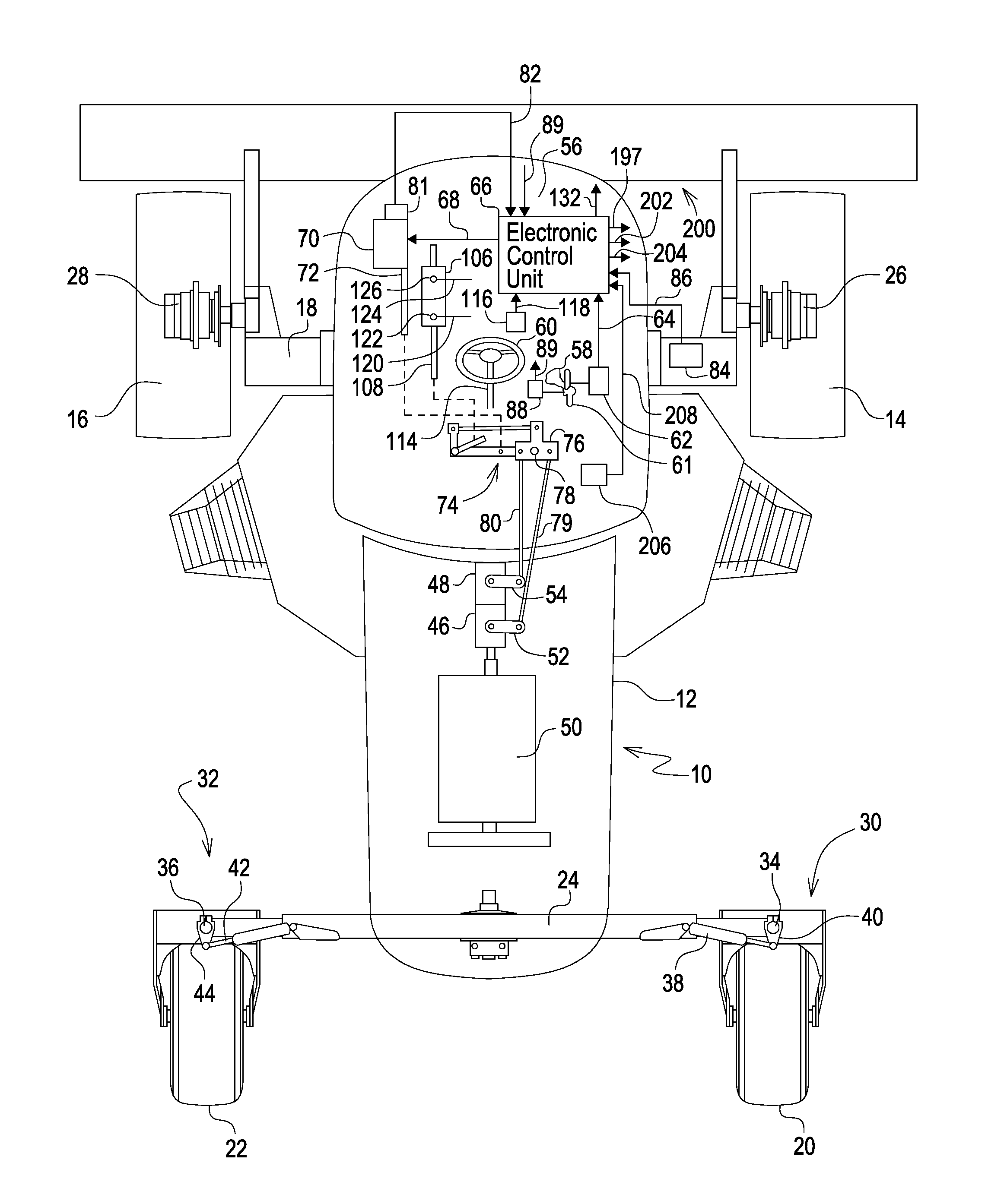
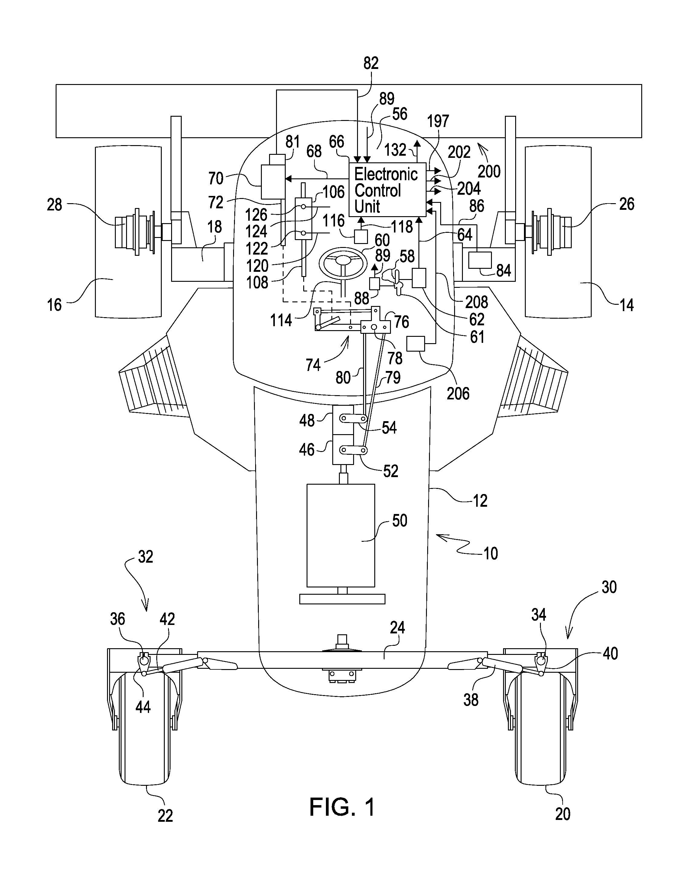
[0017]Referring now to FIG. 1, there is shown a self-propelled agricultural vehicle 10, here shown as being the type used for carrying a forward-mounted implement 200 such as a mower-conditioner, for example. The vehicle 10 is shown schematically and includes a frame 12 supported on right- and left-hand front drive wheels 14 and 16, respectively, mounted to opposite ends of a front axle assembly 18, and right- and left-hand rear ground wheels 20 and 22, respectively, mounted to opposite ends of a rear axle assembly 24.

[0018]The front drive wheels 14 and 16 are respectively driven by right- and left-hand hydraulic motors 26 and 28 forming part of a dual path hydrostatic transmission and can be caused to be driven at different speeds so that the vehicle 10 may be steered. The rear wheels 18 and 20 are respectively carried by right- and left-hand rear wheel assemblies 30 and 32 having respective spindles 34 and 36 mounted in opposite ends of the rear axle assembly 24 for rotating about...


PUM


Abstract

An integrated steering control system includes a primary, automatic and rear control valves. A steering wheel operates the primary steering control valve and is of a type which includes a leakage characteristic. Steering wheel movement is sensed and a signal is sent which results in the automatic steering control valve being operated for adding fluid that supplied to a steering cylinder by the primary steering control valve in order to compensate for leakage, the amount of added fluid being a function of vehicle ground speed. An electric actuator with position feedback is used for ground speed control. Whenever the actuator position shows that the ground speed is set to zero and a switch in the hydro-handle slot shows that the handle is in the Park position, the automatic steering control valve is activated to move the steering cylinder to a neutral, straight ahead position, as determined by a sensor in a mechanical linkage of the steering control.

Description

FIELD OF THE INVENTION[0001]The present invention relates to vehicles having hydrostatically driven front wheels and hydraulically steerable rear wheels and more specifically relates to an integrated steering control system for such vehicles.BACKGROUND OF THE INVENTION[0002]Agricultural machinery is operated under a variety of conditions. As these conditions change, it may be desirable to change the sensitivity of the steering. Steering valves are available with dual displacements, for example, to provide a selectable steering rate. The rate could be selectable as an operator preference or could be automatically selected as a function of a condition such as transmission gear selection or travel speed.[0003]A variable steering rate would be particularly advantageous on a windrower. The dual path hydrostatic drive typically used on windrowers gives them unique handling characteristics. Operator preferences for steering rate vary considerably and may change as driving experience is gai...

Claims


Application Information

Patent Timeline
Patent Type & Authority Patents(United States)
IPC IPC(8): B62D5/09B62D5/093B62D11/00B62D11/04
CPCB62D11/04B62D5/093B62D11/005
Inventor BEBERNES, THOMAS D.O'BRIEN, STEPHEN E.
Owner DEERE & CO
Why Eureka
Try Eureka