
Patient-specific total hip arthroplasty

a technology for total hip arthroplasty and patients, applied in the field of patient-specific total hip arthroplasty, can solve the problems of difficult to orient the guide in the guide will not necessarily key into the correct preoperatively planned location, so as to minimize the reaction force and optimize the range of motion

Active Publication Date: 2015-01-13
HOWMEDICA OSTEONICS CORP
View PDF64 Cites 124 Cited by
  • Summary
  • Abstract
  • Description
  • Claims
  • Application Information

AI Technical Summary

Benefits of technology

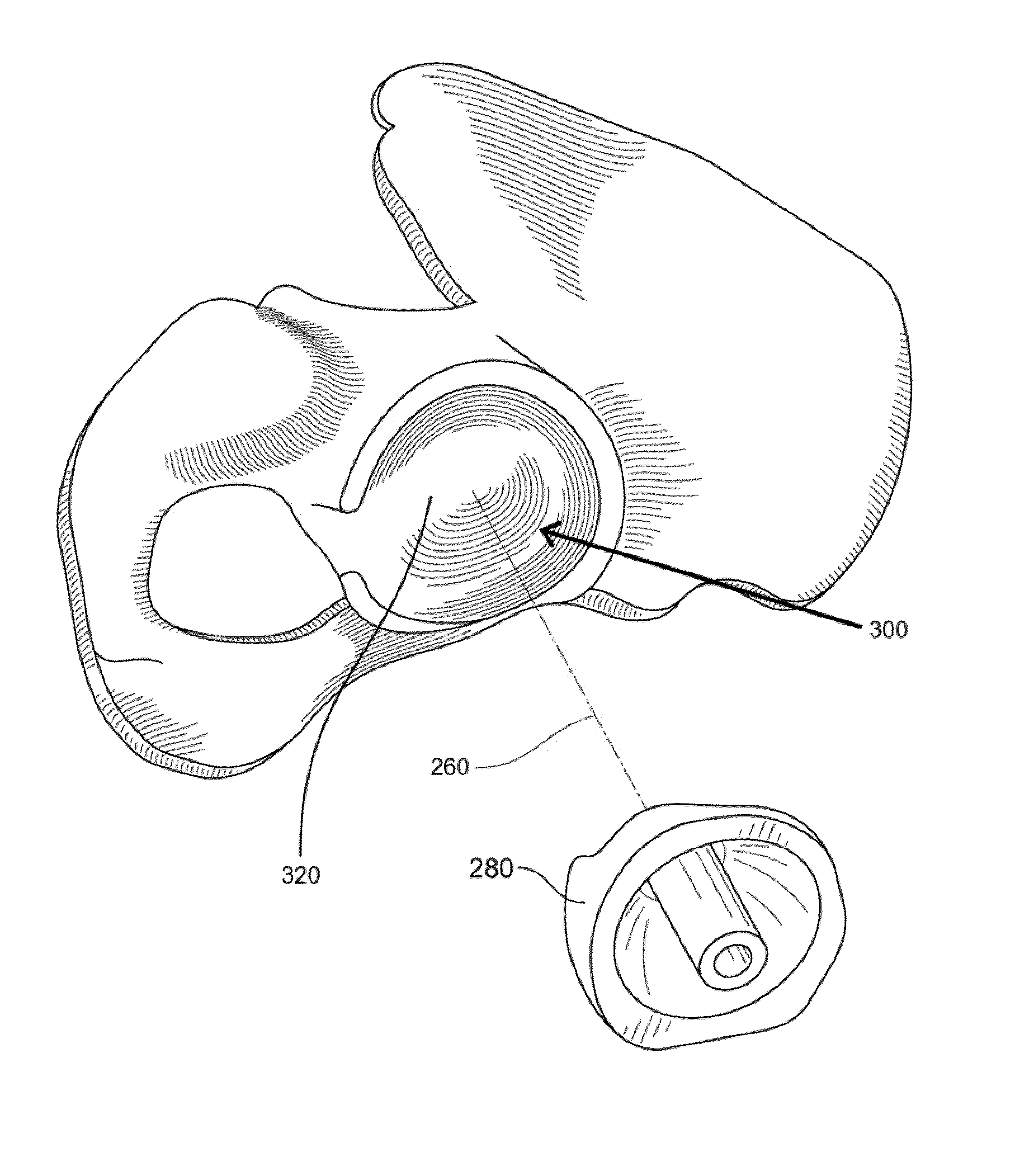
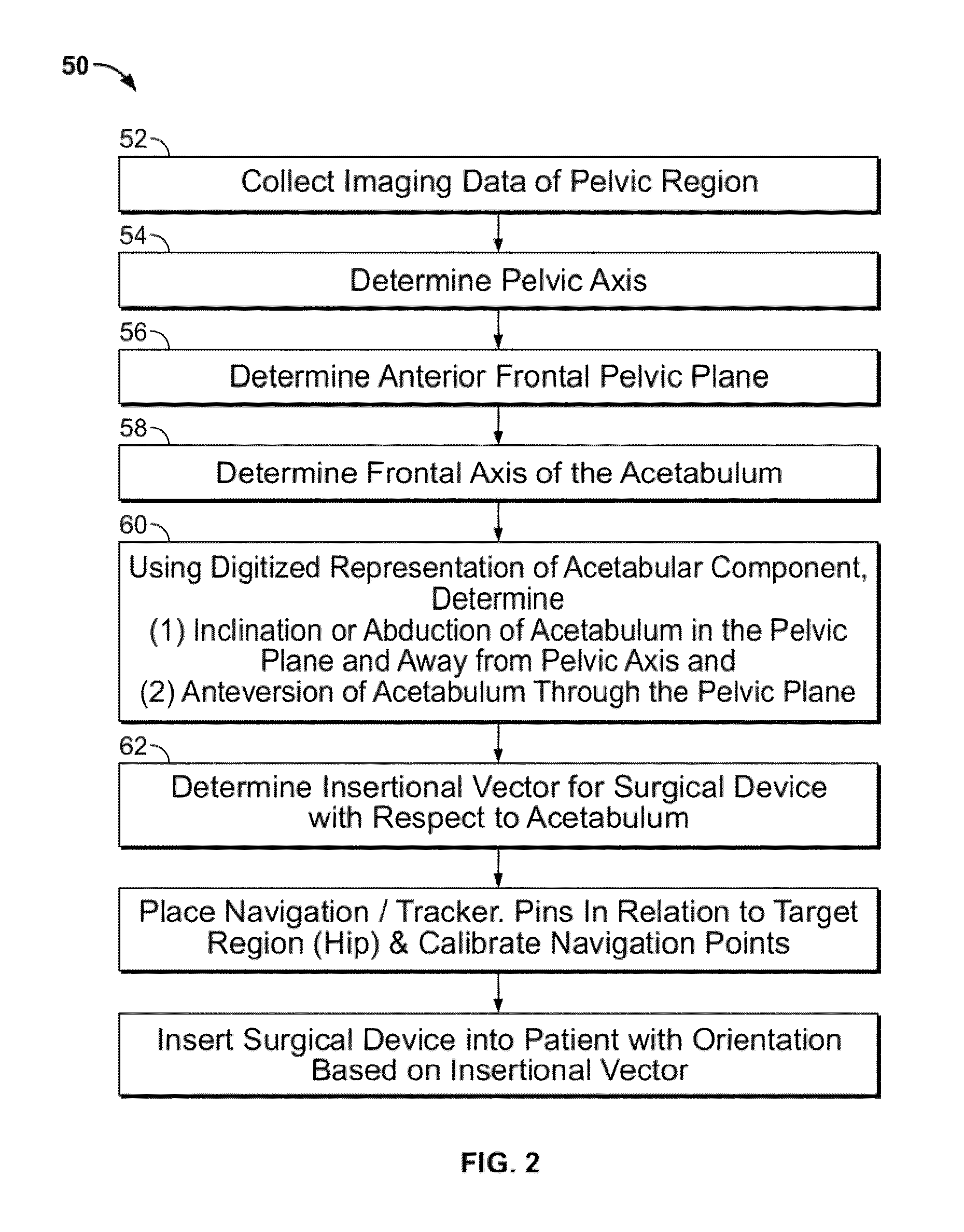
[0028]Another aspect of the present invention is a method of using a patient-specific guide in conjunction with a navigation system for preparation and positioning of an acetabular component. Preoperative images of a patient's pelvic region are taken using computer tomography (“CT”), magnetic resonance imaging (“MRI”), or other imaging methodology. The images are evaluated to determine the correct axis of orientation for the acetabular cup to achieve optimal range of motion for a femoral component and maximum acetabular body coverage while minimizing the reaction forces experienced in the acetabular cup. The image data is manipulated to create a patient-specific 3D model guide depicting the unique negative impression of the contour of the acetabulum with a guide slot having an axis incorporated as a feature in the model. The patient-specific guide may then be manufactured.

Problems solved by technology

Even though the contact surface of the guide is patient-specific, it may still be difficult to orient the guide in a correct preoperatively planned location because of the ovular configuration of the deformed acetabulum.
Even if the guide is rotated in either a clockwise or counterclockwise orientation while adjacent to the acetabulum, the guide will not necessarily key into the correct preoperatively planned location.

Method used


Image

  • Patient-specific total hip arthroplasty
  • Patient-specific total hip arthroplasty
  • Patient-specific total hip arthroplasty

Examples


Embodiment Construction

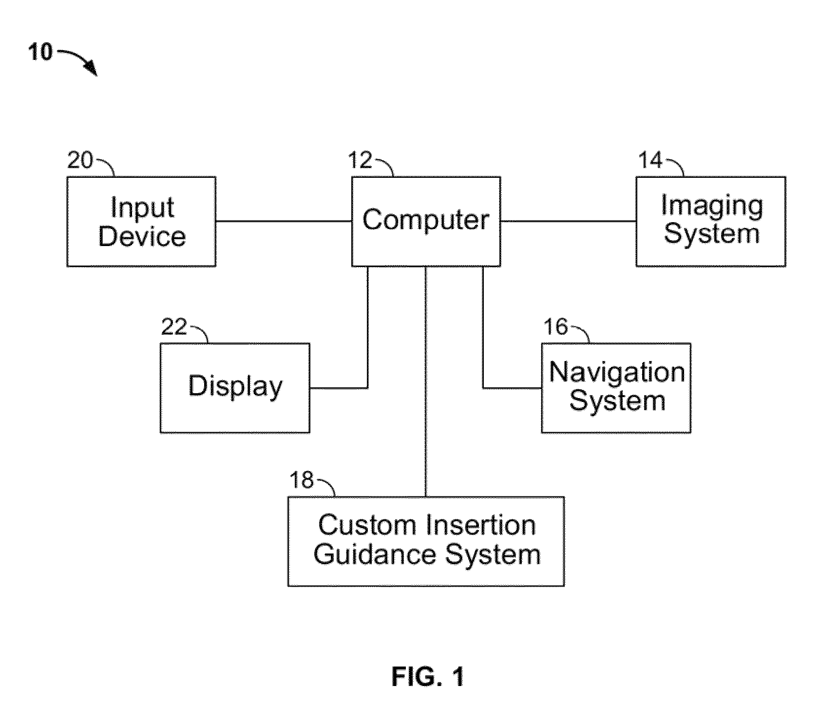
[0054]FIG. 1 is a block diagram of a surgical guidance system 10, in accordance with the present invention. Referring to FIG. 1, the system 10 includes a computer 12 coupled to an imaging system 14, a navigation system 16 and an instrumentation guidance system 18. The system 10 further includes an input device 20 and a display 22.

[0055]The imaging system 14 is a conventional imaging device for providing medical images, such as X-rays, fluoroscopic, CT, MRI, etc., of a patient's anatomical regions.

[0056]The navigation system 16 is a conventional device including positional sensors or trackers for attachment to a patient and surgical instruments for reporting the location and orientation of the patient's anatomy and a surgical instrument in 3D space.

[0057]The computer 12 is a conventional processor including a memory and capable of exchanging data and control signals with the imaging system 14 and the navigation system 16 for obtaining images of the patient, and for tracking data repr...


PUM


Abstract

Disclosed herein are systems and methods for performing total hip arthroplasty with patient-specific guides Pre-operative images of a pelvic region of a patient are taken in order to predefine the structure of the guides and corresponding implants. From the obtained image data an insertional vector for implanting an acetabular implant or component into an acetabulum of the patient is determined, wherein the insertional vector is coaxial with a polar axis of the acetabular component. Also from the obtained image data, a superior surface of the guides and implants can be shaped to match the acetabulum of the patient. A nub portion extending outwardly from the superior surface of the guides and implants is shaped to substantially match the shape of a fovea of the acetabulum. A guide portion of the guides forming a slot has a longitudinal axis coaxial with the determined insertional vector of a corresponding acetabular component.

Description

CROSS REFERENCE TO RELATED APPLICATION[0001]This application claims the benefit of the filing date of U.S. Provisional Patent Application No. 61 / 356,324 filed Jun. 18, 2010, the disclosure of which is hereby incorporated herein by reference.BACKGROUND OF THE INVENTION[0002]The present invention relates to providing instruments for the alignment of an acetabular cup within the acetabulum, which may include preoperative imaging to create a patient-specific guide for predefining the resection of the acetabulum to receive the acetabular cup.[0003]The success of hip joint replacement surgery, which is a well-accepted treatment for arthritic conditions of the hip, depends upon preoperative planning and also the proper intraoperative placement of reamers, alignment instruments, and implants, for example, in order for the function of the joint to be optimized biologically and biomechanically. In particular, in hip replacement surgery, successful hip reconstruction is predicated upon restori...

Claims


Application Information

Patent Timeline
Patent Type & Authority Patents(United States)
IPC IPC(8): A61B17/58A61B17/17A61B19/00A61F2/30A61F2/34G16H20/40
CPCA61B17/1746A61B19/50A61F2/34A61B2019/504A61F2002/30945A61F2002/30948A61F2002/30952A61F2002/30957A61F2002/3412A61B2034/104A61B34/10G16H50/50A61F2002/30943G16H20/40A61F2/30942A61F2/4609A61B2034/107A61B2034/108A61B34/20A61B2034/2068A61B90/37A61B2090/374A61B2090/376A61B2090/3762G16H20/30
Inventor BONO, JAMES V.AXELSON, JR., STUART L.BASTIAN, ADAM
Owner HOWMEDICA OSTEONICS CORP
Learn More