
System and method for printing interference patterns having a pitch in a lithography system

a technology of interference pattern and lithography system, which is applied in the field of interferometric lithography, can solve the problems of difficult to achieve fringe contrast across a large image field, difficult to use conventional masks, patterning arrays, reticles, etc., and achieve the effect of reducing beam shear

Inactive Publication Date: 2015-01-13
ASML HLDG NV
View PDF106 Cites 1 Cited by
  • Summary
  • Abstract
  • Description
  • Claims
  • Application Information

AI Technical Summary

Benefits of technology

This approach enables the production of high-resolution patterns with consistent contrast across the entire field, matching or surpassing conventional lens-based lithography capabilities, and allows for variable pitch printing by optimizing each interferometer in a stack for specific pitches.

Problems solved by technology

It is very difficult to use conventional masks, reticles, and patterning arrays to achieve resolutions at the nanometer scale, such as 30-100 nm.
However, it is sometimes very difficult to achieve a desirable fringe contrast across a large image field when using these systems.

Method used


Image

  • System and method for printing interference patterns having a pitch in a lithography system
  • System and method for printing interference patterns having a pitch in a lithography system
  • System and method for printing interference patterns having a pitch in a lithography system

Examples


Embodiment Construction

[0027]While specific configurations and arrangements are discussed, it should be understood that this is done for illustrative purposes only. A person skilled in the pertinent art will recognize that other configurations and arrangements can be used without departing from the spirit and scope of the present invention. It will be apparent to a person skilled in the pertinent art that this invention can also be employed in a variety of other applications.

[0028]It is noted that references in the specification to “one embodiment”, “an embodiment”, “an example embodiment”, etc., indicate that the embodiment described may include a particular feature, structure, or characteristic, but every embodiment may not necessarily include the particular feature, structure, or characteristic. Moreover, such phrases are not necessarily referring to the same embodiment. Further, when a particular feature, structure, or characteristic is described in connection with an embodiment, it would be within th...


PUM

PropertyMeasurementUnit
wavelengthaaaaaaaaaa

Abstract

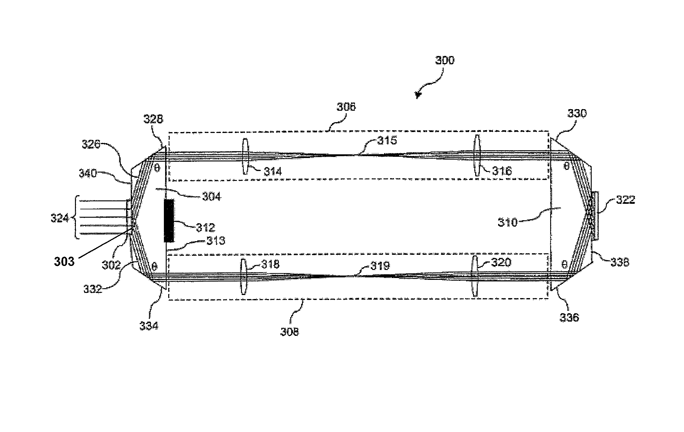
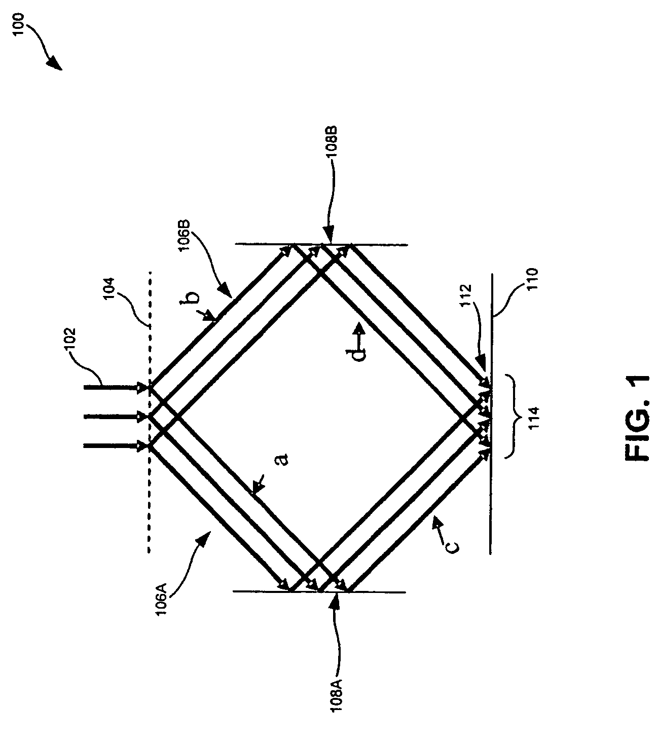
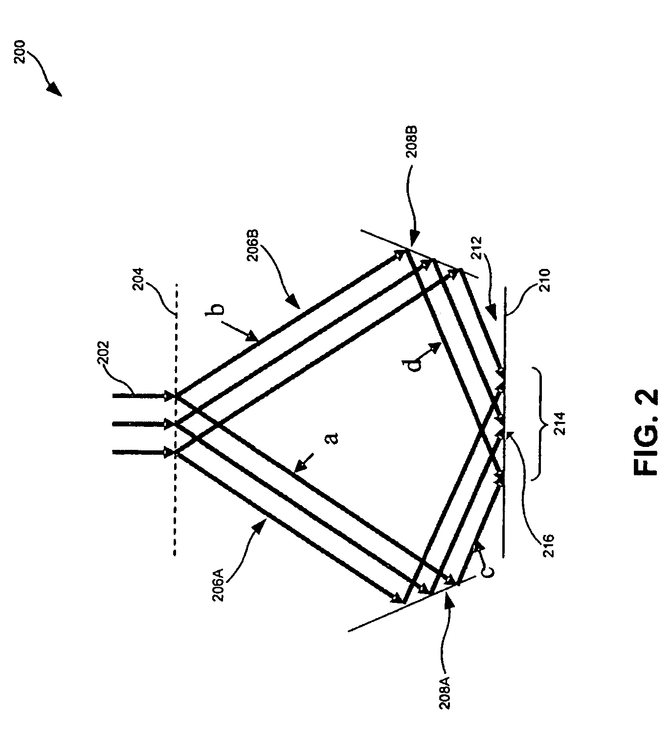
An interferometric lithography system produces a pattern having a sharp field edge and minimal optical path length difference. Light passes through a beamsplitter into an input prism. The two beams produced by the beamsplitter are reflected off respective surfaces of the input prism toward a substrate prism. The substrate prism is symmetric to the input prism such that the incidence angle at an image plane is approximately equal to the beamsplitter diffraction angle. Alternatively, light passes through a beamsplitter into a prism. The two beams produced by the beamsplitter are reflected off respective surfaces of the prism toward an output surface of the prism, such that the incidence angle at the output surface is approximately equal to the beamsplitter diffraction angle. A plurality of these interferometers can be stacked, each being optimized for a given pitch, such that the stack provides a variable pitch interferometry system.

Description

BACKGROUND OF THE INVENTION[0001]1. Field of the Invention[0002]The present invention relates to lithographic systems, and more particularly to interferometric lithography.[0003]2. Related Art[0004]A lithographic apparatus is a machine that applies a desired pattern onto a substrate or part of a substrate. A lithographic apparatus can be used, for example, in the manufacture of flat panel displays, integrated circuits (ICs) and other devices involving fine structures. In a conventional apparatus, a patterning device, which is commonly referred to as a mask or a reticle, can be used to generate a circuit pattern corresponding to an individual layer of a flat panel display (or other device). This pattern can be transferred onto all or part of the substrate (e.g., a glass plate), by imaging onto a layer of radiation-sensitive material (e.g., photoresist) provided on the substrate.[0005]Instead of a circuit pattern, the patterning means can be used to generate other patterns, for exampl...

Claims


Application Information

Patent Timeline
Patent Type & Authority Patents(United States)
IPC IPC(8): G03B27/52G03F7/20
CPCG03F7/70408
Inventor SHMAREV, YEVGENIY KONSTANTINOVICH
Owner ASML HLDG NV
Learn More