Optical article for illuminating building interiors with sunlight

a technology for building interiors and optical articles, applied in the field of natural lighting, can solve the problems of wedge-shaped deformations (crazes) propagating within the material, internal tir structures, and little control over spacing, depth and exten

Active Publication Date: 2015-01-13
S V V TECH INNOVATIONS
View PDF42 Cites 21 Cited by
  • Summary
  • Abstract
  • Description
  • Claims
  • Application Information

AI Technical Summary

Problems solved by technology

An organic solvent is applied on the panel surface while a tensile stress is applied to a panel which results in generation of wedge-shaped deformations (crazes) which propagate within the material.
However, such method of forming internal TIR structures offers little control over the spacing, depth and extent of the crazes, as well as can substantially compromise the structural integrity or rigidity of the panel.
However, the use of prior art light redirecting devices for daylighting purposes can be deficient in that such devices only provide light redirection in one angular dimension, whereas the significant seasonal and hourly positional changes of the sun are two-dimensional (i.e., changes in the elevation and azimuth angle).

Method used


Image

  • Optical article for illuminating building interiors with sunlight
  • Optical article for illuminating building interiors with sunlight
  • Optical article for illuminating building interiors with sunlight

Examples


example 1

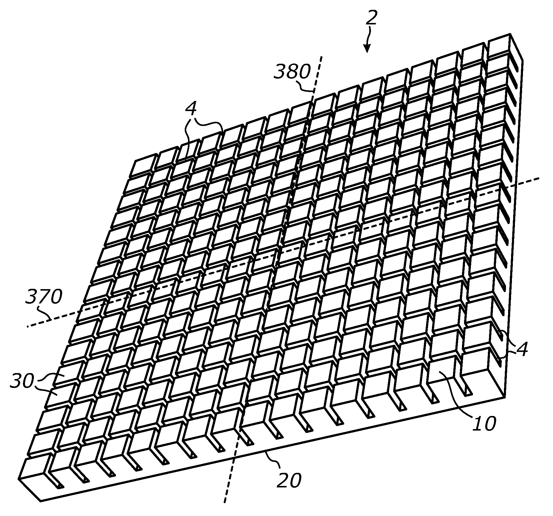
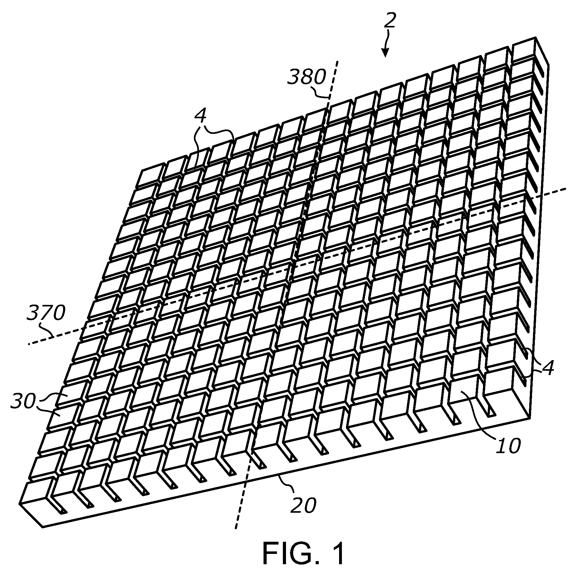
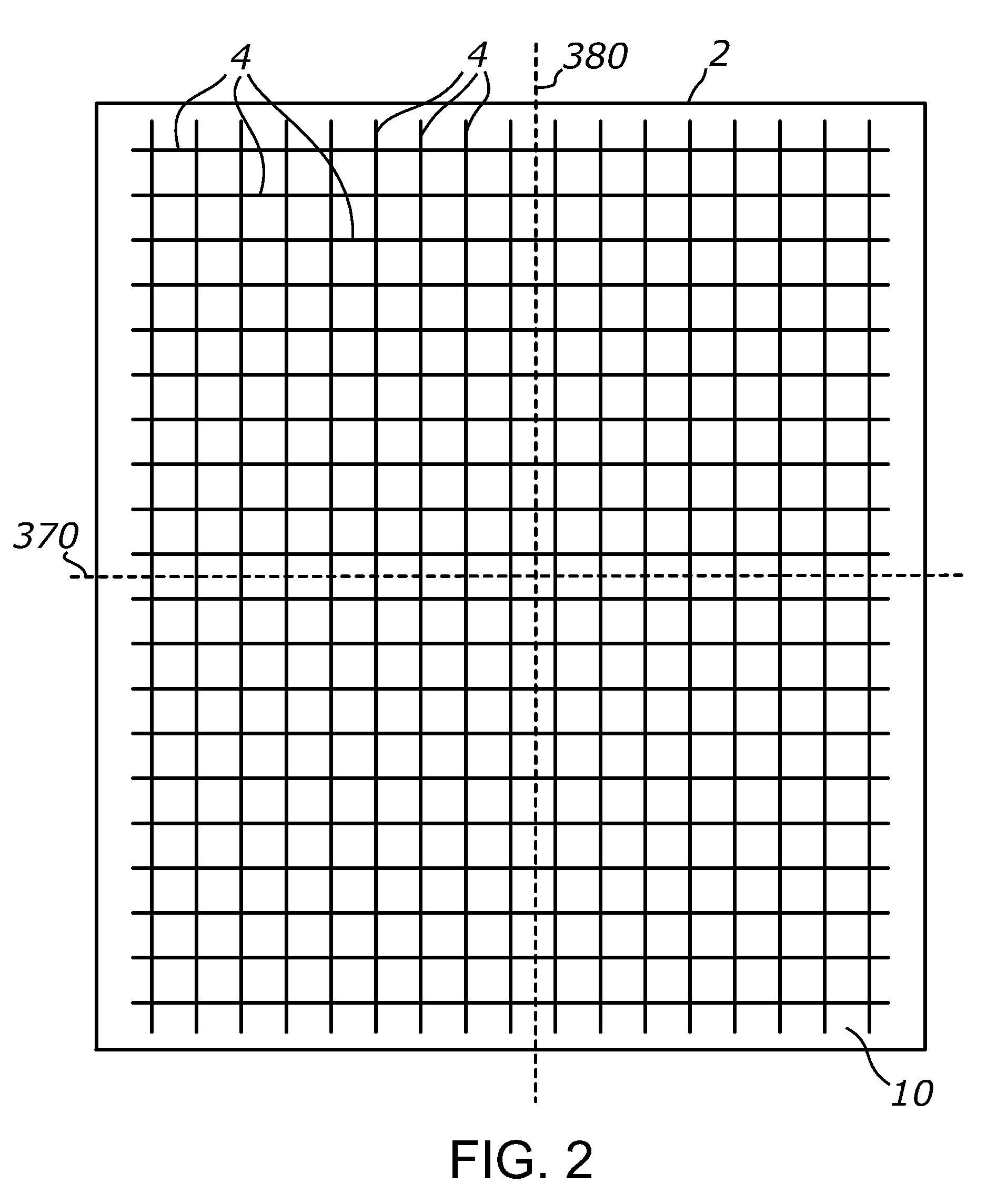
[0112]FIG. 30 shows a photograph of a prototype sheet 2 made by cutting a grid of narrow channels 4 in a 0.25-inch acrylic (PMMA) sheet by means of material ablation using a 60-W CO2 laser. The laser emits a narrow (about 6 mm) parallel beam with the wavelengths of about 10 micrometers. The laser beam was made scanning across the surface of sheet 2 using a Cartesian gantry system and a system of mirrors and focused on the surface of the acrylic sheet using a 0.75″-diameter ZnSe lens having a focal length of 2″. The laser beam scanning speed was selected at about 14 mm / sec.

[0113]A first array of parallel channels was cut in one of the smooth surfaces of the acrylic sheet after which a second array of parallel channels was cut in a perpendicular direction in the same surface. The selective material ablation by scanning the focused laser beam across the acrylic sheet surface has resulted in the formation of a rectangular grid of narrow and deep channels in the surface. The laser cuttin...

example 2

[0117]Laser-cut channels were produced according to the method described above in a ¼″ acrylic sheet having a light-scattering, matte-finish surface. The illumination of such light-scattering variation of sheet 2 with an off-axis beam with approximately 45° incidence angle has produced a broad, relatively evenly distributed, scattered beam of light spanning approximately ±60° from a normal to sheet 2 in the prevailing plane of beam propagation. The total angular span of the scattered beam was around 120°. For comparison, the off-axis parallel beam illumination of a similar light-diffusing acrylic sheet having no channels 4 and no TIR walls has resulted in much narrower scattered beam (less than 60°) and light propagation only towards the opposing direction from the light source, exhibiting notably unequal light distribution on the target. Accordingly, the formation of laser-cut TIR channels in the surface of acrylic sheet has produced a light beam which angular spread is approximate...


PUM

PropertyMeasurementUnit
angleaaaaaaaaaa
dihedral angleaaaaaaaaaa

Abstract

A sheet-form light-redirecting optical article for illuminating building interiors with sunlight. At least one embodiment comprises a sheet of optically transmissive rigid material, preferably Poly(methyl methacrylate), in which a plurality of deep and narrow parallel channels are formed and arranged in two perpendicular arrays. Each channel has opposing walls configured for reflecting light by means of a Total Internal Reflection (TIR). At least a portion of off-axis rays incident onto the surface of the sheet is redirected by the TIR walls of the light-guiding channels. At least one embodiment comprises a grid formed by intersecting specular reflectors and further comprises a light diffusing element optically coupled to the grid. Disclosed also are a method for making the intersecting arrays of light-redirecting channels.

Description

CROSS-REFERENCE TO RELATED APPLICATIONS[0001]This application claims priority from U.S. provisional application Ser. No. 61 / 691,264 filed on Aug. 21, 2012, incorporated herein by reference in its entirety, and U.S. provisional application Ser. No. 61 / 775,678 filed on Mar. 10, 2013, incorporated herein by reference in its entirety.STATEMENT REGARDING FEDERALLY SPONSORED RESEARCH OR DEVELOPMENT[0002]Not ApplicableINCORPORATION-BY-REFERENCE OF MATERIAL SUBMITTED ON A COMPACT DISC[0003]Not ApplicableNOTICE OF MATERIAL SUBJECT TO COPYRIGHT PROTECTION[0004]A portion of the material in this patent document is subject to copyright protection under the copyright laws of the United States and of other countries. The owner of the copyright rights has no objection to the facsimile reproduction by anyone of the patent document or the patent disclosure, as it appears in the United States Patent and Trademark Office publicly available file or records, but otherwise reserves all copyright rights wh...

Claims


Application Information

Patent Timeline
Patent Type & Authority Patents(United States)
IPC IPC(8): G02B17/00G02B27/00B29D11/00E06B9/24F21S11/00G02B5/18
CPCG02B5/0205G02B5/0268G02B5/0278F21S11/002B29D11/00E06B9/24B29D11/00663G02B5/1857G02B2207/123E06B2009/2417F21S11/007F21V13/04F21V11/06E06B2009/2482E06B2009/2488G02B5/0221G02B17/006G02B19/0019
Inventor VASYLYEV, SERGIY
Owner S V V TECH INNOVATIONS
Why Eureka
Try Eureka