Unlock instant, AI-driven research and patent intelligence for your innovation.

Sensor for measuring hydrocarbon content in a flow of gas in a purge line

a technology of hydrocarbon content and sensor, which is applied in the direction of electric control, specific gravity measurement, instruments, etc., can solve the problems of increased consumption of internal combustion engines, poor exhaust gas values, and air/fuel mixtures which are usually too rich in the engin

Inactive Publication Date: 2015-01-20
VITESCO TECH GERMANY GMBH
View PDF18 Cites 1 Cited by
  • Summary
  • Abstract
  • Description
  • Claims
  • Application Information

AI Technical Summary

Benefits of technology

The present invention provides a sensor that can accurately measure the hydrocarbon content in the gas stream of an internal combustion engine. This is particularly useful in a scavenging line from a hydrocarbon accumulator to the engine. The accumulator is filled with activated carbon, which is effective and economical. The sensor uses ultrasonic waves to determine the mass flow rate of the hydrocarons based on the temperature difference and the temperature sum. This is a simple and fast computing operation that can be carried out by the engine controller or processor on the sensor.

Problems solved by technology

However, there are also a series of further sources for undesired exhaust gases in motor vehicles.
This control by the λ probe occurs relatively slowly, with the result that when the valve in the scavenging line opens according to the model stored in the engine controller, an air / fuel mixture which is significantly too rich is usually burnt in the engine.
This leads to increased consumption by the internal combustion engine and to very poor exhaust gas values.
Particularly in hybrid vehicles with very low exhaust gas emission and an internal combustion engine, which is often stationary, the problem occurs of the controlled scavenging of the hydrocarbon accumulator.

Method used


Image

  • Sensor for measuring hydrocarbon content in a flow of gas in a purge line
  • Sensor for measuring hydrocarbon content in a flow of gas in a purge line
  • Sensor for measuring hydrocarbon content in a flow of gas in a purge line

Examples


Embodiment Construction

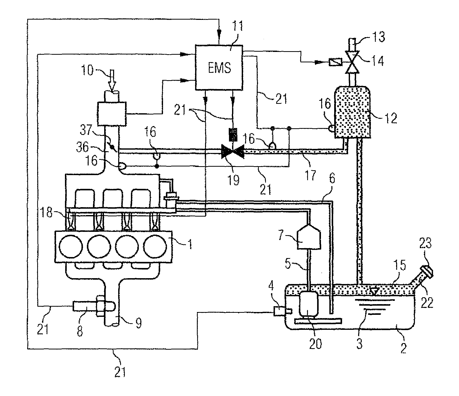
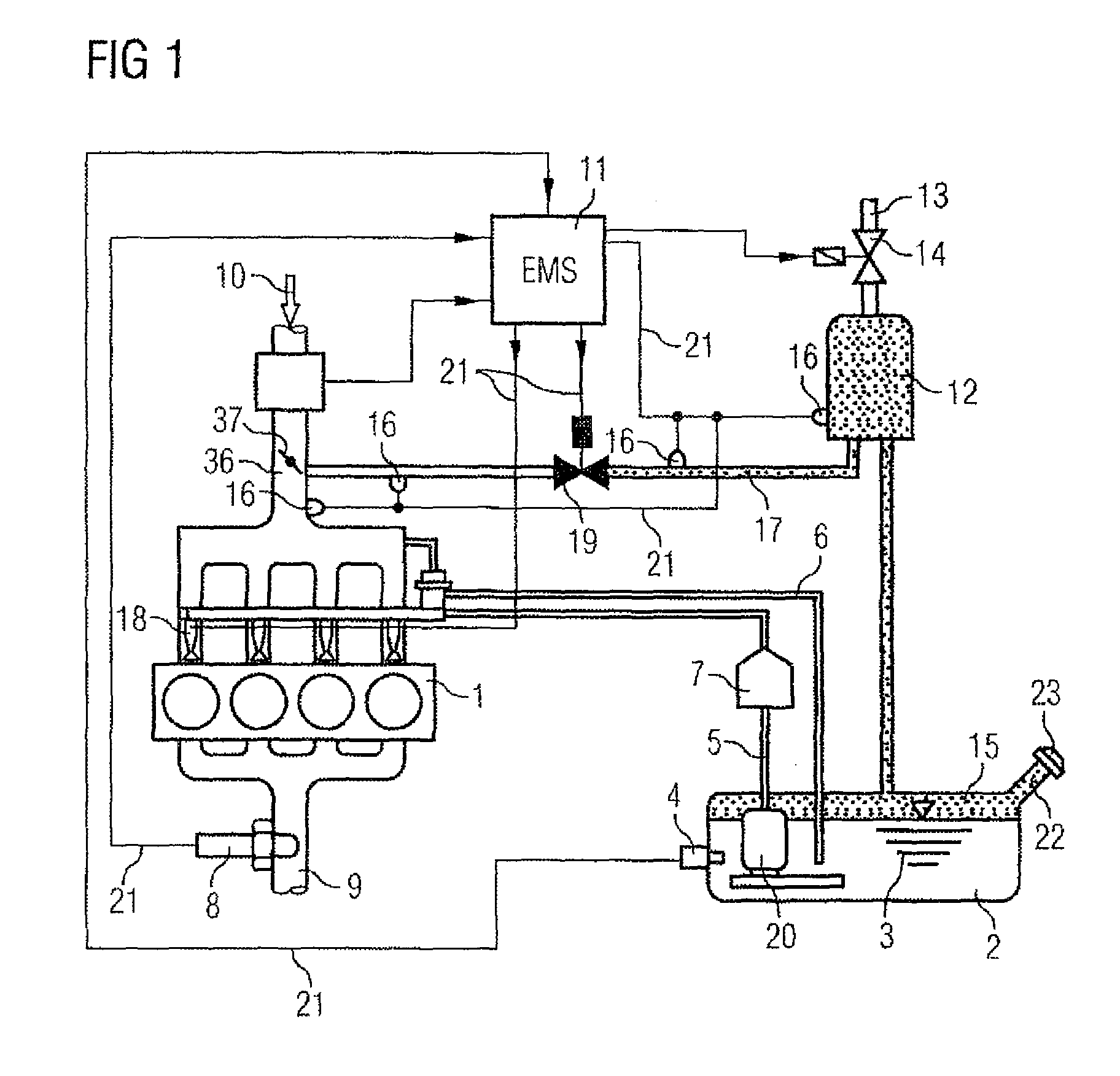
[0033]FIG. 1 shows an internal combustion engine 1 which is connected to a fuel tank 2 by a fuel line 5. A fuel feeder unit 20 in the fuel tank 2 feeds fuel 3 via the fuel line 5 and a fuel filter 7 to the internal combustion engine 1 where the fuel 3 is injected into an intake section 36 with injection valves 18 and is burnt in the internal combustion engine 1. The exhaust gases of the combustion process are conveyed away from the engine through an exhaust section 9. A λ probe 8, which monitors the exhaust gases and is intended to permit optimum combustion of the fuel / air mixture, can be seen in the exhaust section 9. For this purpose, the λ probe 8 is connected via an electrical signal line 21 to an electronic engine controller (EMS) 11. Furthermore, an air inlet 10, which leads to the intake section 36 in which a throttle valve 37 is arranged, can be seen in FIG. 1.

[0034]Fuel 3 can be seen in the fuel tank 2. In order to differentiate various fuel qualities, a sensor 4 for detect...


PUM

PropertyMeasurementUnit
temperatureaaaaaaaaaa
thermal capacityaaaaaaaaaa
thermal conductivityaaaaaaaaaa

Abstract

A sensor for the measurement of the hydrocarbon content in a flow of gas in a purge line. The sensor can measure the hydrocarbon content in the flow of gas in the purge line from a hydrocarbon storage device to an internal combustion engine. The sensor has at least one heating element and at least one thermal detector, with the heating element heating the flow of gas while the thermal detector determines the temperature of the flow of gas, which temperature is evaluated as a measurement of the hydrocarbon content in the flow of gas.

Description

PRIORITY CLAIM[0001]This is a U.S. national stage of application No. PCT / EP2007 / 059175, filed on Sep. 3, 2007 which claims priority to the German Application No.: 10 2007 033 144.6, Filed: Jul. 13, 2007; the content of both incorporated herein by reference.BACKGROUND OF THE INVENTION[0002]1. Field of the Invention[0003]The invention relates to a sensor for measuring hydrocarbon content in a gas stream in a scavenging or purging line.[0004]2. Prior Art[0005]A central objective in the development of modem motor vehicles is to reduce the exhaust gases which are output by the motor vehicle. In the last few years, efforts have mainly concentrated on the cleaning of the combustion gases. However, there are also a series of further sources for undesired exhaust gases in motor vehicles. These sources include the fuel tank of the motor vehicle. Fuels such as, for example, premium gasoline which are stored in the fuel tank contain a series of highly volatile hydrocarbons. These include, for e...

Claims


Application Information

Patent Timeline
Patent Type & Authority Patents(United States)
IPC IPC(8): G01N7/00F02M25/08G01N27/18F02D41/00
CPCG01N2291/011F02D41/0045G01N2291/0215F02D2200/0611F02M25/0836G01N27/18
Inventor BIERL, RUDOLFGRASS, PHILIPPEHEINRICH, STEPHANWEIGL, MANFREDWILDGEN, ANDREAS
Owner VITESCO TECH GERMANY GMBH