Method of performing osteotomy

a technology of osteotomy and bone grafting, applied in the field of osteotomy, can solve the problems of compromising the ultimate effectiveness of the procedure, affecting reducing the safety of the patient, so as to facilitate separation and removal

Inactive Publication Date: 2015-01-27
TRIMED
View PDF13 Cites 13 Cited by
  • Summary
  • Abstract
  • Description
  • Claims
  • Application Information

AI Technical Summary

Benefits of technology

[0009]In one form, the invention is directed to a method of performing an osteotomy. The method includes the steps of: a) providing a guide assembly; b) placing the guide assembly in operative relationship to a bone to be cut so that the guide assembly defines first and second guide edges that are in fixed relationship to each other to each guide movement of a cutting tool; c) guiding the cutting tool along each of the first and second guide edges to produce first and second cut lines in the bone to facilitate separation and removal of a fragment of the bone from between first and second bone surfaces formed respectively at the first and second cut lines; d) separating the bone fragment so that a gap with a first width is formed between the first and second bone surfaces; and e) changing the width of the gap to be less than the first width.

Problems solved by technology

This may lead to situations where more or less than an optimal amount of bone is initially removed.
In the latter case, one or more additional cuts may be required, thereby complicating the procedure.
In the former case, the ultimate effectiveness of the procedure may be compromised.
Further, unguided cutting may produce irregular surfaces on the separate bone parts that do not precisely match when they are drawn together.
This may result in a deviation from the desired degree of shortening.
This may also adversely affect the time of healing and / or the effectiveness of the fusion of the bone parts.

Method used


Image

  • Method of performing osteotomy
  • Method of performing osteotomy
  • Method of performing osteotomy

Examples


Embodiment Construction

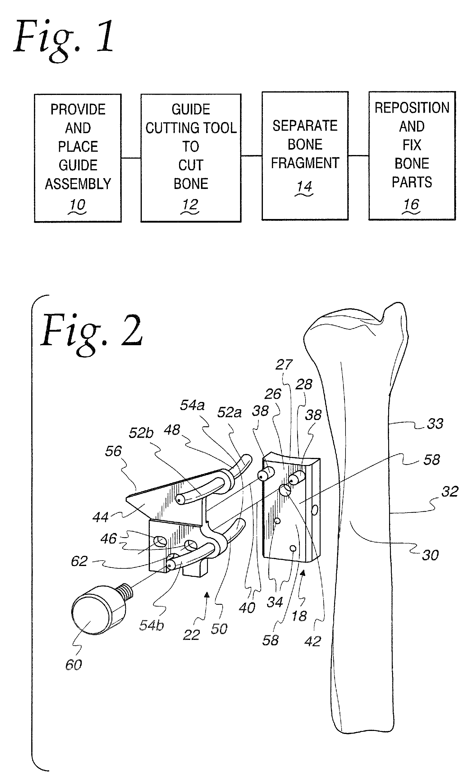
[0049]In FIG. 1, a flow diagram representation of a method of performing an osteotomy, according to the present invention, is shown. According to the invention, a guide assembly is provided and placed in operative relationship to a bone to be cut, such as an ulnar bone, as shown at block 10 in FIG. 1. The guide assembly defines first and second guide edges that are in fixed relationship to each other to guide movement of a cutting tool.

[0050]As shown at block 12, the cutting tool is guided along each of the first and second guide edges to cut the bone so as to produce first and second cut lines in the bone to facilitate separation and removal of a wedge-shaped fragment of the bone from between first and second bone surfaces formed at the separate cut lines.

[0051]As shown at block 14, the bone fragment defined by using the cutting tool is separated and removed so that a gap of a first width is formed between the first and second bone surfaces.

[0052]Separate bone parts, upon which the...


PUM


Abstract

A method of performing an osteotomy including the steps of: providing a guide assembly; placing the guide assembly in operative relationship to a bone to be cut so that the guide assembly defines first and second guide edges that are in fixed relationship to each other to each guide movement of a cutting tool; guiding the cutting tool along each of the first and second guide edges to produce first and second cut lines in the bone to facilitate separation of a fragment of the bone from between first and second bone surfaces formed respectively at the first and second cut lines; separating the bone fragment so that a gap with a first width is formed between the first and second bone surfaces; and changing the width of the gap to be less than the first width.

Description

BACKGROUND OF THE INVENTION[0001]1. Field of the Invention[0002]This invention relates to osteotomies and, more particularly, to a method for facilitating predictable bone removal in terms of size, shape, and location.[0003]2. Background Art[0004]Ulnar shortening osteotomies have been performed by surgeons for decades to address ulnocarpal impaction. More recently, a less invasive technique has been developed that involves the strategic removal of 2-5 mm of the ulna at its neck region.[0005]Heretofore, it has been common to perform this procedure freehand with a motorized saw. The optimal cutting location is identified primarily visually by the surgeon, who makes an initial cut along a first line. A subsequent cut is made gauged from the location of the first cut to separate a bone fragment. The ulnar surfaces formed by the separate cuts are then drawn together. The separate bone parts, on which the surfaces are formed, are thereafter maintained together using headless screws.[0006]...

Claims


Application Information

Patent Timeline
Patent Type & Authority Patents(United States)
IPC IPC(8): A61B17/56A61B17/15A61B17/17A61B17/88
CPCA61B17/152A61B17/8866A61B2017/1782A61B17/1782
Inventor BUDOFF, JEFFREY E.
Owner TRIMED
Why Eureka
Try Eureka