Spark plug

a technology of spark plugs and nickel layers, applied in spark plugs, machines/engines, mechanical equipment, etc., can solve the problems of large stress difference between the ground electrode, interfere with the proper spark discharge of the spark plug, etc., to prevent the separation of the outer-lateral-side nickel layer particularly effectively and assuredly

Active Publication Date: 2015-02-03
NGK SPARK PLUG CO LTD
View PDF11 Cites 2 Cited by
  • Summary
  • Abstract
  • Description
  • Claims
  • Application Information

AI Technical Summary

Benefits of technology

[0009]In view of the above circumstances, it is an object of the present invention to provide a spark plug having a nickel layer applied to a ground electrode so as to effectively reduce a stress difference between the nickel layer (notably, outer-lateral-side nickel layer) and the ground electrode and assuredly prevent separation of the nickel layer from the ground electrode.
[0047]It is possible according to configuration 9 to prevent separation of the outer-lateral-side nickel layer particularly effectively and assuredly by the synergistic effect of configuration 3 and configuration 4, 5 or 6.

Problems solved by technology

In the case where the boundary region of the nickel layer abruptly changes in thickness, the boundary region of the outer-lateral-side nickel layer cannot follow deformation (expansion or contraction) of the ground electrode caused due to heating / cooling cycles during operation of the internal combustion engine so that there occurs a large stress difference between the outer-lateral-side nickel layer and the ground electrode.
Similarly, the boundary region of the outer-lateral-side nickel layer cannot follow bending of the ground electrode so that there occurs a large stress difference between the outer-lateral-side nickel layer and the ground electrode in the case where the boundary region of the nickel layer abruptly changes in thickness.
By such a large stress difference, the boundary region of the outer-lateral-side nickel layer may be separated from the ground electrode and get into the spark discharge gap to thereby interfere with proper spark discharge of the spark plug.

Method used


Image

  • Spark plug
  • Spark plug
  • Spark plug

Examples


Embodiment Construction

[0054]The present invention will be described in detail below with reference to the drawings.

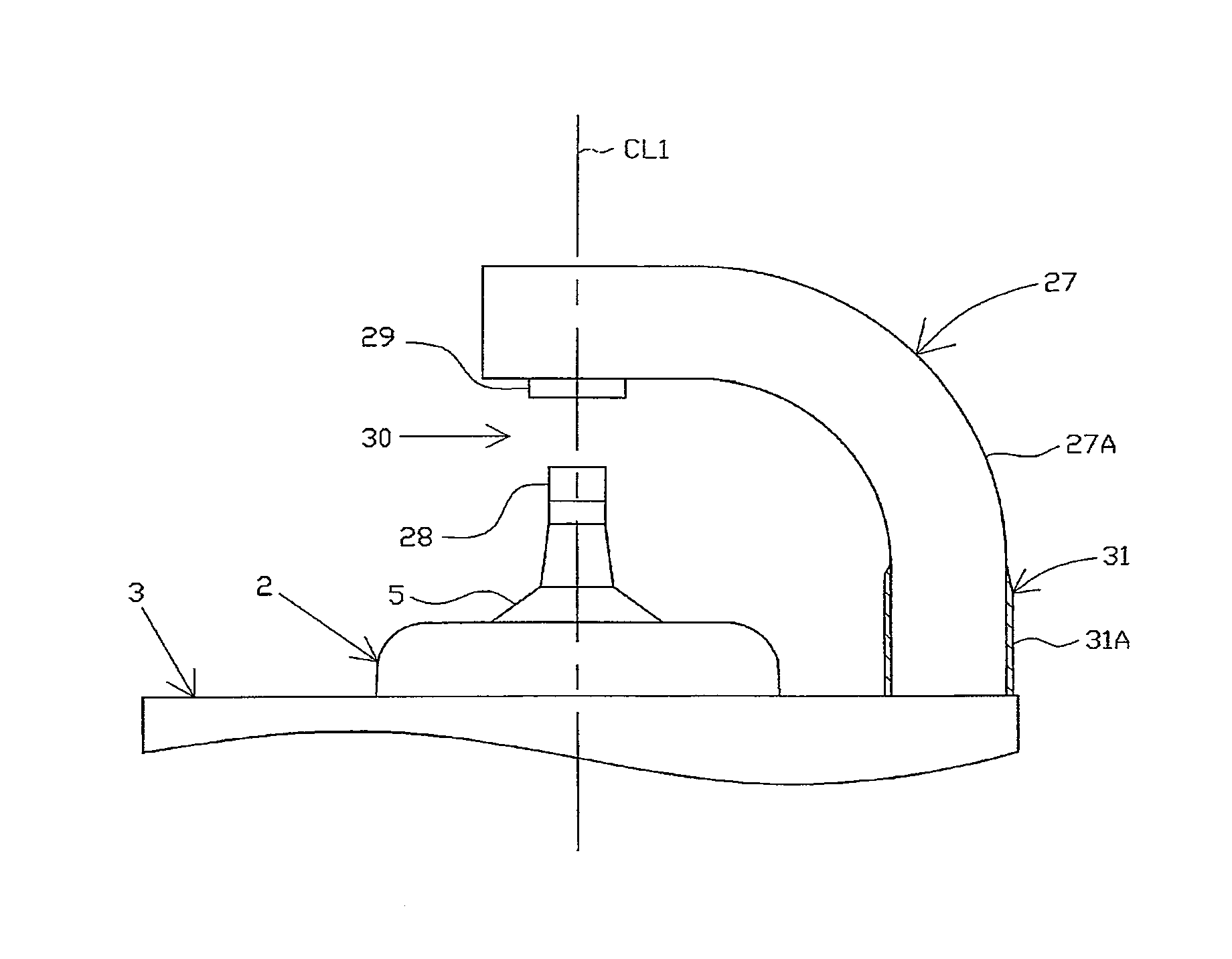
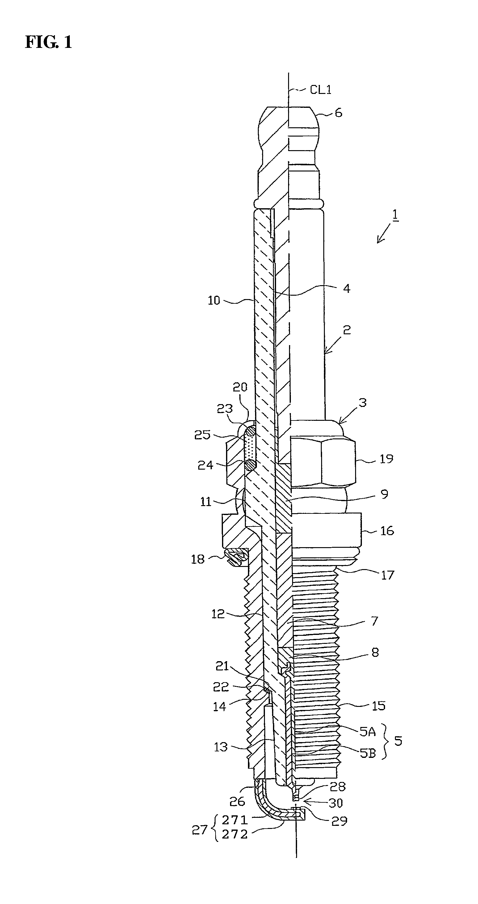
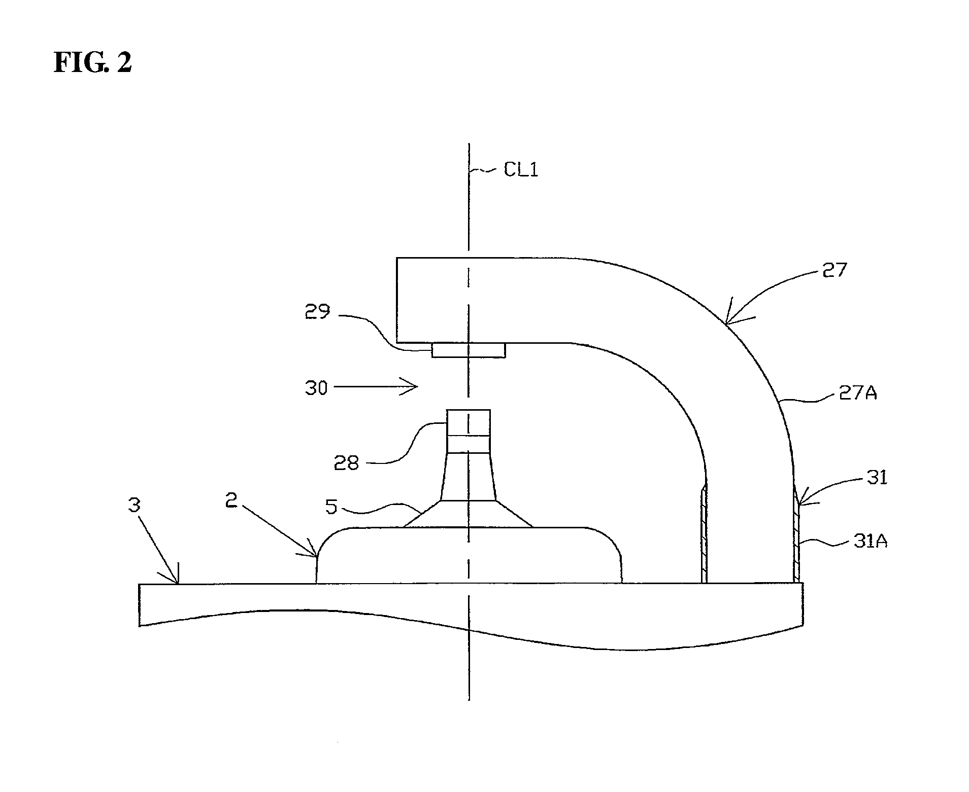
[0055]Herein, the following exemplary embodiment specifically refers to a spark plug 1 for use by mounting to a combustion apparatus (such as an internal combustion engine or a fuel cell processing device). It is noted that the direction of an axis CL1 of the spark plug 1 corresponds to the vertical direction of FIG. 1 where the front and rear sides of the spark plug 1 are shown on the bottom and top sides of FIG. 1, respectively.

[0056]As shown in FIG. 1, the spark plug 1 includes a ceramic insulator 2 as a cylindrical insulator and a cylindrical metal cell 3 holding therein the ceramic insulator 2.

[0057]The ceramic insulator 2 is made of sintered alumina as is generally known and has an outer shape including a rear body portion 10 formed on a rear side thereof, a large-diameter portion 11 formed front of the rear body portion 10 and protruding radially outwardly, a middle body portion 12 fo...


PUM

PropertyMeasurementUnit
temperatureaaaaaaaaaa
distanceaaaaaaaaaa

Abstract

A spark plug includes a metal shell, a ground electrode joined to a front end portion of the metal shell and a nickel layer formed on the ground electrode, wherein the ground electrode has a base material exposed region in which a base material of the ground electrode is exposed; and wherein the nickel layer includes an outer-lateral-side nickel layer located on an outer lateral surface of the ground electrode at a position adjacent to the base material exposed region and satisfies a condition of LA≧25 μm, where LA is a length from a first part of the outer-lateral-side nickel layer having a thickness equal to 80% of a maximum thickness of the outer-lateral-side nickel layer to a second part of the outer-lateral-side nickel layer having a thickness equal to 20% of the maximum thickness of the outer-lateral-side nickel layer in a longitudinal direction of the ground electrode.

Description

FIELD OF THE INVENTION[0001]The present invention relates to a spark plug for use in an internal combustion engine or the like.BACKGROUND OF THE INVENTION[0002]Hereinafter, the term “front” refers to a spark discharge side with respect to the direction of an axis of a spark plug; and the term “rear” refers to a side opposite the front side.[0003]A spark plug is mounted to an internal combustion engine (sometimes simply referred to as “engine”) etc. and used to ignite an air-fuel mixture in a combustion chamber of the engine. The spark plug generally includes an insulator formed with an axial hole in the direction of an axis of the spark plug, a center electrode inserted in a front side of the axial hole, a metal shell arranged on an outer circumference of the insulator and a ground electrode joined to a front end portion of the metal shell. The ground electrode is bent at a substantially middle portion thereof toward the center electrode such that a distal end portion of the ground ...

Claims


Application Information

Patent Timeline
Patent Type & Authority Patents(United States)
IPC IPC(8): H01T13/32H01T13/39H01T13/20
CPCH01T13/20H01T13/32H01T13/39
Inventor KODAMA, KAZUHIRONASU, HIROAKI
Owner NGK SPARK PLUG CO LTD
Why Eureka
Try Eureka