Lightweight integrated rear suspension and drive enclosure for a ridden motorized vehicle

a technology for ridden motor vehicles and rear suspensions, which is applied in the direction of jet propulsion mounting, cycle equipment, cycle equipment, etc., can solve the problems of increasing road noise, high manufacturing costs, and heavy weight of the motor with the suspension, so as to reduce the unsprung weight of the ridden vehicle, reduce the complexity of manufacture, and reduce the cost of manufacture.

Inactive Publication Date: 2015-02-10
HERO MOTOCORP
View PDF99 Cites 5 Cited by
  • Summary
  • Abstract
  • Description
  • Claims
  • Application Information

AI Technical Summary

Benefits of technology

[0005]Unsprung weight is the mass of every component on a ridden vehicle not supported by the suspension. Such components may include the wheels, brake systems, axel, and suspension system. In systems such as those described by JP 2010-228627 this also includes the motor and the gear system. A ridden vehicle having a lighter unsprung weight will have unsprung components moving more readily with the road bumps and irregularities, maintaining the traction between the road and the wheel, and therefore, provide a more uniform grip and improved performance. A ridden vehicle having a heavier unsprung weight will have unsprung components which will absorb less of the bumps and irregularities in the road and, therefore, vibrations will be transmitted to the rest of the vehicle, the rider, and passengers. For the same reason road noise will increase with vehicles having a heavier unsprung weight as well. Therefore, there is presently a need for a ridden motorized vehicle, such as a motor scooter, motorcycle, ATV, tricycle, snowmobile, or lawn tractor, having a lightweight rear suspension and drive enclosure system.
[0007]There is presently a need for a drive system in ridden vehicles which provides both rear suspension with an enclosed drive transfer system, such as a drive shaft, belt, or chain, while reducing the unsprung weight of the system. Also, there is presently a need for a lightweight rear suspension and drive enclosure system for a ridden motorized vehicle which has fewer parts, to reduce the cost and complexity of manufacturing, installation and maintenance of such systems. Presently disclosed is a simple two piece enclosure wherein the drive transfer system is totally enclosed, has integrated chain tensioner, has one drive transfer system, such as a drive shaft, chain, or belt between a motor assembly output shaft and rear wheel axle, has lower unsprung weight, and provides easy service access to the drive transfer system.
[0011]Such a monocoque structural drive enclosure provides a drive enclosure with fewer parts compared to prior art drive enclosures. The presently disclosed monocoque structural drive enclosure provides for reduced cost of manufacture, installation and maintenance, as well as reduced complexity of manufacture, installation and maintenance. The presently disclosed monocoque structural drive enclosure also provides for reduced unsprung weight of the ridden vehicle, thereby improving ride quality and reducing road noise. Also, the presently disclosed ridden vehicle, having a drive enclosure with a pivot point aligned with the motor assembly output shaft, provides a vehicle providing a single drive chain or belt between the sprocket on the motor assembly output shaft and the sprocket on the rear wheel axle while maintaining the distance between the motor assembly output shaft and the rear wheel axle, as opposed to a dual drive chain or belt system of the prior art. Therefore, a ridden vehicle of the presently disclosed design provides for reduced complexity of manufacture, installation and maintenance, as well as reduced cost for all three phases.
[0012]In some embodiments, the ridden vehicle may be a motor scooter having a motor assembly disposed on the main chassis frame, while also providing a flat board, step-through construction. This embodiment provides a motor scooter with reduced unsprung weight while also providing the step-through convenience of traditional motor scooters, which traditionally have their motor assembly disposed on the rear wheel axle. This easily maintains the attraction of the motor scooter to both men and women alike, while greatly reducing unsprung weight with the motor assembly attached to the frame of the motor scooter instead of the rear wheel axle. The greatly reduced unsprung weight provides a motor scooter with an improved ride quality and reduced road noise. In some embodiments, the ridden vehicle may be an electric scooter or a hybrid scooter.
[0013]In some embodiments, the monocoque structural drive enclosure is disposed on one side of the motorized vehicle, such as a motor scooter, motorcycle, ATV, tricycle, snowmobile, or lawn tractor, providing for easy access and maintenance to the rear wheel, allowing the rear wheel to be removed without disassembling the drive enclosure. In other embodiments, the presently disclosed monocoque structural drive enclosure may be assembled on both sides of the vehicle, having a dual drive chain or belt, providing for increased power to be transmitted between the motor assembly and the rear wheel. Furthermore, the motor assembly, as discussed above, may have an integrated or attached gear system disposed between the motor shaft and the output sprocket at the first end of the drive enclosure, the output shaft for the gear system aligned with the pivot point of the drive enclosure at the first end of the drive enclosure.
[0014]Also disclosed is a ridden vehicle comprising a frame, at least one motor assembly attached to the frame, and a motor assembly having an output shaft. The motor assembly may be attached to a motor assembly mount portion, removable from the frame. Such a configuration provides for a more simple installation and manufacturing system for assembling the ridden vehicle. The ridden vehicle may also have a drive enclosure having a first end and a second end, the first end having a frame connection point aligned with the output shaft of the motor assembly, and the second end having a wheel connection point, the drive enclosure adapted to pivot about the frame connection point. The ridden vehicle further comprises a wheel connected to the wheel connection point at the second end of the drive enclosure and a linkage apparatus disposed between the output shaft of the motor assembly and the wheel connected at the second end of the drive enclosure, the linkage apparatus adapted to transfer power from the output shaft of the motor assembly to the drive wheel. The linkage apparatus between the output shaft of the motor and the wheel may be a drive shaft, a chain, or a belt.

Problems solved by technology

This type of system is costly, heavy, and complex to manufacture and maintain.
Such designs described, for example, by Japanese Patent Application Publication JP 2010-228627 are complex, and the motion of the motor with the suspension increases unsprung weight to the detriment of ride quality.
For the same reason road noise will increase with vehicles having a heavier unsprung weight as well.
These systems require at least two chains and a double intermediary sprocket on the swingarm pivot axis, providing a system which is complex and difficult to manufacture and service.
Some prior art systems have a sprocket on the output shaft of the motor assembly and a final sprocket mounted on the rear wheel concentric with the axle which allows for loosening and tightening of the chain during suspension movement, caused by the variation in distance between the engine and wheel sprockets as the suspension moves, and, in turn, causing noise, wear, and imprecise drive delivery.
Such prior art systems have many components comprised within the drive train of the motorized vehicles and are, therefore, complex to manufacture, install, and maintain.

Method used


Image

  • Lightweight integrated rear suspension and drive enclosure for a ridden motorized vehicle
  • Lightweight integrated rear suspension and drive enclosure for a ridden motorized vehicle
  • Lightweight integrated rear suspension and drive enclosure for a ridden motorized vehicle

Examples


Embodiment Construction

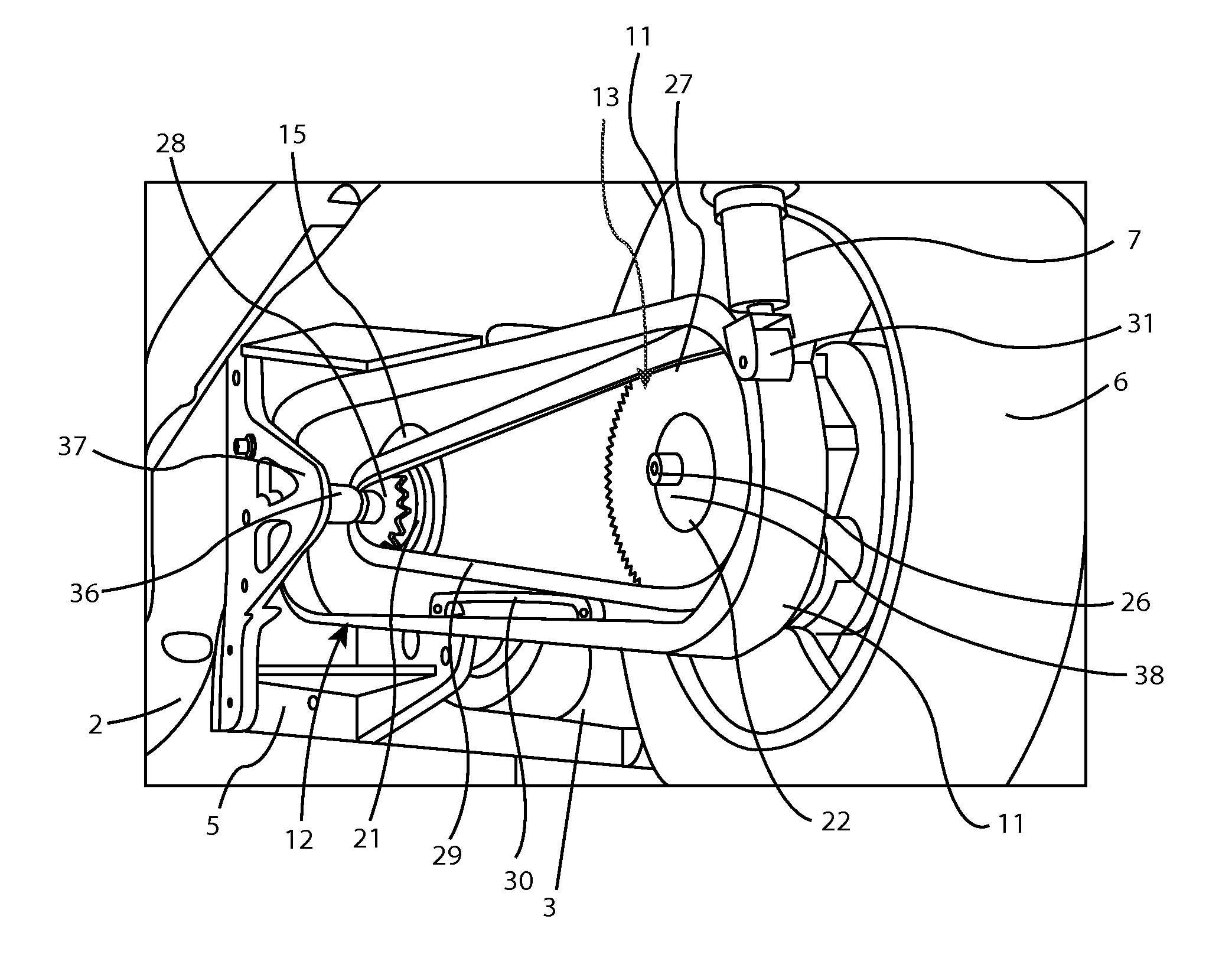
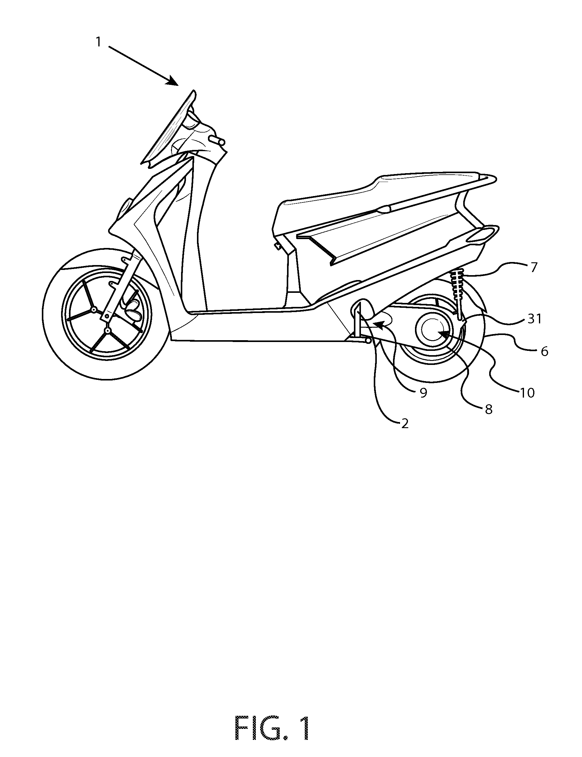
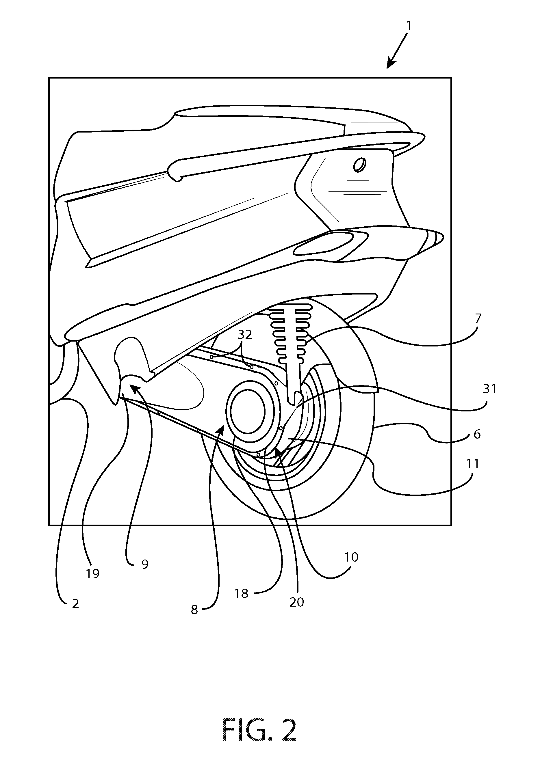
[0029]Referring to FIGS. 1 and 2, disclosed is a ridden motorized vehicle 1 having a monocoque drive enclosure 8. The monocoque drive enclosure having a first end 9 and a second end 10 extending from the main chassis frame 2 of the motorized vehicle 1 to the rear wheel 6 of the motorized vehicle 1. A rear shock absorber 7 may be attached to a shock absorber mount 31 at the second end 10 of the monocoque drive enclosure 8, with the opposite end of the shock absorber mounted to the main chassis frame 2. The shock absorber mount 31 may be integrated into the monocoque drive enclosure 8 or may be separate and attached to the monocoque drive enclosure 8. The shock absorber 7 may be attached to the second end 10 of the drive enclosure 8, as shown in the Figures. Alternatively, the shock absorber 7 may be attached to the drive enclosure 8 at the first end 9 or at some other position along the drive enclosure 8.

[0030]In some embodiments, the shock absorber 7 may be attached to the rear whee...


PUM


Abstract

A ridden motorized vehicle such as a motorized scooter, motorcycle, ATV, tricycle, snowmobile, or lawn tractor, having a driven rear wheel may be equipped with an enclosed chain or belt drive enclosure having a first end and a second end and an inner enclosure and an outer enclosure, such that the inner enclosure has the rear suspension member and the rear wheel mounted at the second end, and concentrically pivots at the first end on the motor assembly output shaft of a motor assembly fastened to or comprising part of the main vehicle frame, and the outer enclosure pivoted on another bearing co-linear with the motor assembly output shaft, but mounted on a removable section of, or attachment to, said frame.

Description

RELATED APPLICATIONS[0001]The present application claims priority to and the benefit of U.S. Provisional Patent Application No. 61 / 582,814, filed on Jan. 3, 2012, which is incorporated herein by reference.BACKGROUND AND SUMMARY[0002]Presently disclosed is a rear suspension and drive enclosure for a ridden motorized vehicle. The presently disclosed rear suspension and drive enclosure may be used with any ridden motorized vehicle having a driven axle pivotally attached to the frame of the motorized vehicle, the driven axle operably connected to a motor power source. Such ridden motorized vehicles may include motor scooters, motorcycles, all-terrain-vehicles, tricycles, snowmobiles, and lawn tractors.[0003]Ridden motorized vehicles, such as those disclosed herein, generally comprise a frame, a power system, and at least one drive wheel. The at least one wheel may provide traction with the ground directly, or may be part of a track system such as with a snowmobile. The power from the po...

Claims


Application Information

Patent Timeline
Patent Type & Authority Patents(United States)
IPC IPC(8): B62K25/02B62K11/00B62K11/04B62K25/28
CPCB62K11/00B62K25/283B62K11/04B62K2202/00B60L2200/12B60L2270/142B60L2270/145B62K2204/00Y02T10/70
Inventor BUELL, ERIKSTEFANELLI, ANTHONYFOX, JOHNBUNNE, JONATHANBATTAGLINI, GIANCARLOANTCZAK, CHADIWINSKI, DEAN
Owner HERO MOTOCORP
Why Eureka
Try Eureka