Interior lining

a technology for interiors and linings, applied in the field of interior linings, can solve the problems of not being able to use waste heat of the motor to heat the interior of the overall vehicle and aircraft, and wasting time and energy for the engine to release sufficient heat, etc., and achieve the effect of heating the interior of the vehicle and aircraft very quickly and independently

Active Publication Date: 2015-02-10
NBHX TRIM
View PDF24 Cites 9 Cited by
  • Summary
  • Abstract
  • Description
  • Claims
  • Application Information

AI Technical Summary

Benefits of technology

[0013]In a preferred embodiment, the heating layer is laminated onto the upper layer so that a planar connection is formed. The use of a natural material as the upper layer, in particular leather or textile, is particularly advantageous so as to guide the heat released from the heating layer towards the outside as effectively as possible and, at the same time, to ensure a pleasant appearance and easy workability. With the use of leather it is also advantageous that the starting material can be cut to size in accordance with the forms of the interior lining and that any seams can be formed at the connection points and edges of the individual parts. In a preferred embodiment, the heating layer is arranged in the surface regions between the seams of the upper layer. For alternative applications with reduced requirements for surface quality, a film or artificial leather can also be used instead of leather.
[0025]Alternatively, the heating layer can also first be pre-laminated onto the carrier to form a carrier / layer composite, and the upper layer can then be press-laminated, membrane-laminated or vacuum-laminated onto the carrier / layer composite. In embodiments in which a foam layer is used, the heating layer can be arranged, surrounded by foam, between the upper layer and the carrier, and the parts can be press-laminated, membrane-laminated or vacuum-laminated together. The component produced by this method has the same advantageous above-described effects.

Problems solved by technology

A drawback of previous methods for heating vehicle interiors is that, in particular at low temperatures in winter, a considerable length of time passes before the engine releases sufficient heat to heat the vehicle interior by means of ventilation.
In particular in the case of diesel vehicles, a very long period of time generally elapses before the air can be heated, and therefore additional electrical heating devices are already provided in the ventilation duct for this purpose.
In vehicles not driven by means of an internal combustion engine, for example electric cars, it is not possible overall to use waste heat of the motor to heat the interior, since the electric motor does not generate sufficient heat.
The heaters installed previously in the region of the seats or steering wheel are merely suitable for heating specific body parts in contact therewith, but are unsuitable for heating the vehicle interior.
A drawback of auxiliary heaters of this type is that, when fuel is combusted, malodorous waste gases which are harmful to health are produced.
In particular, if auxiliary heaters are used in closed spaces, such as garages or underground car parks, the ambient air becomes highly contaminated within just a short space of time.

Method used


Image

  • Interior lining
  • Interior lining
  • Interior lining

Examples


Embodiment Construction

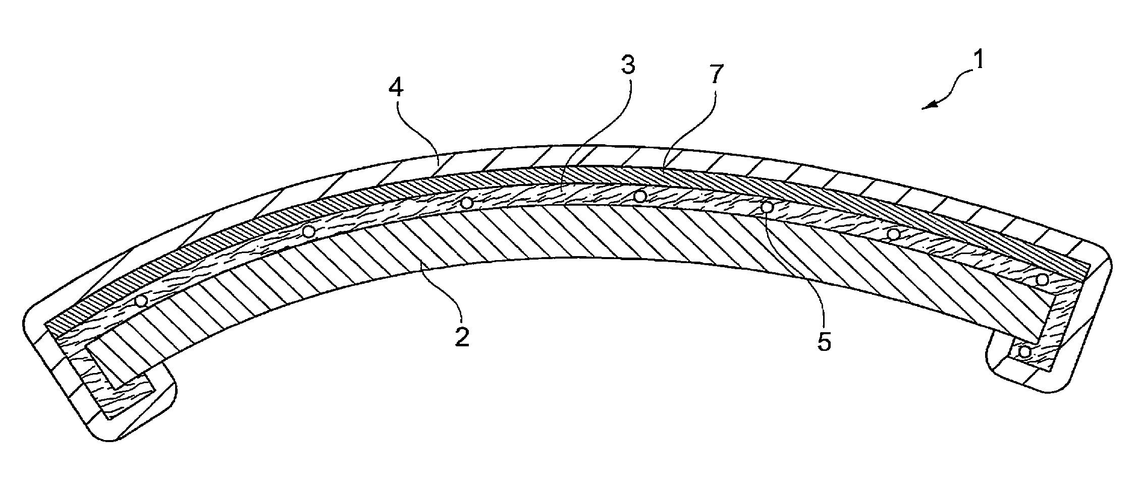
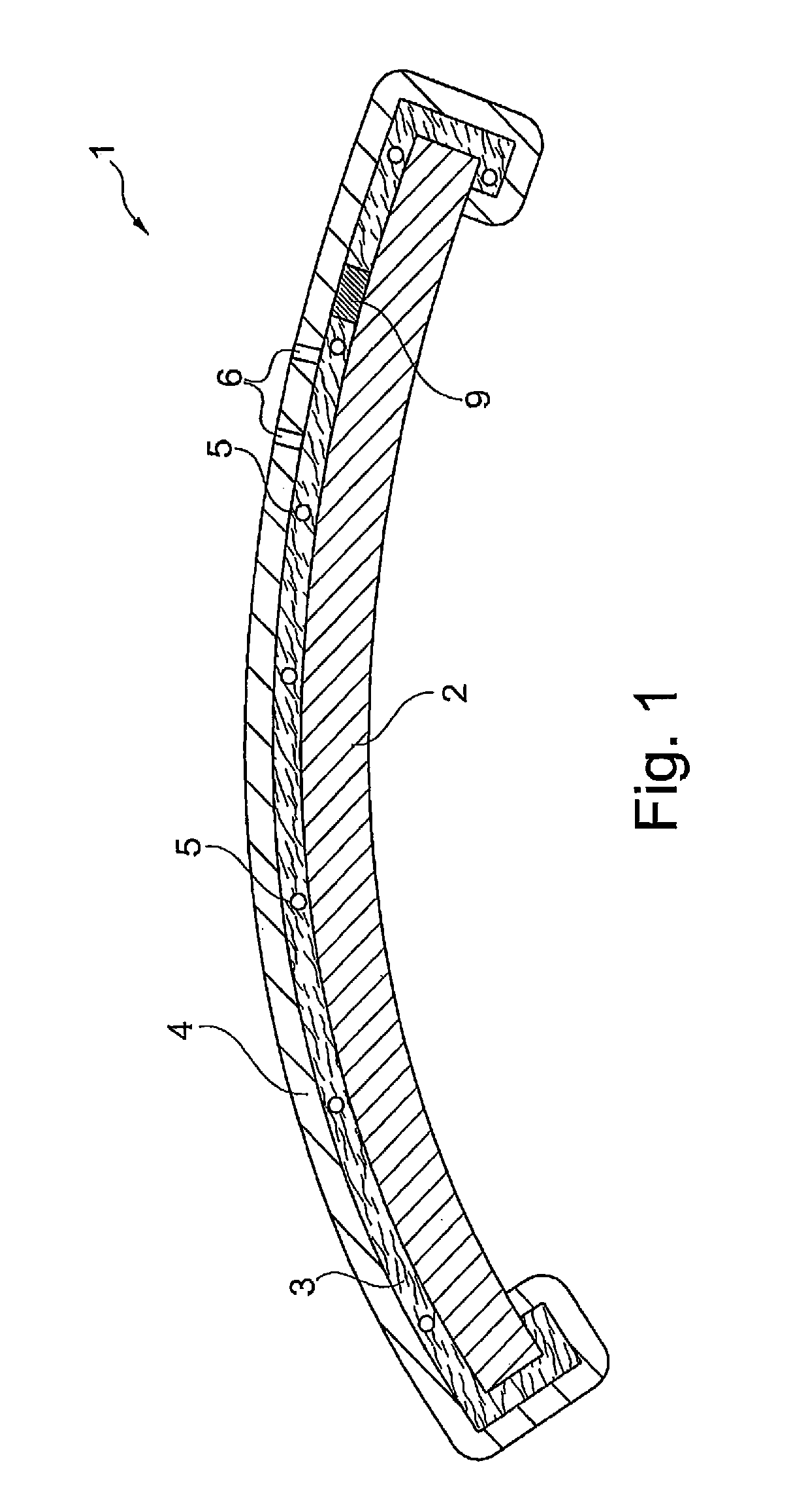
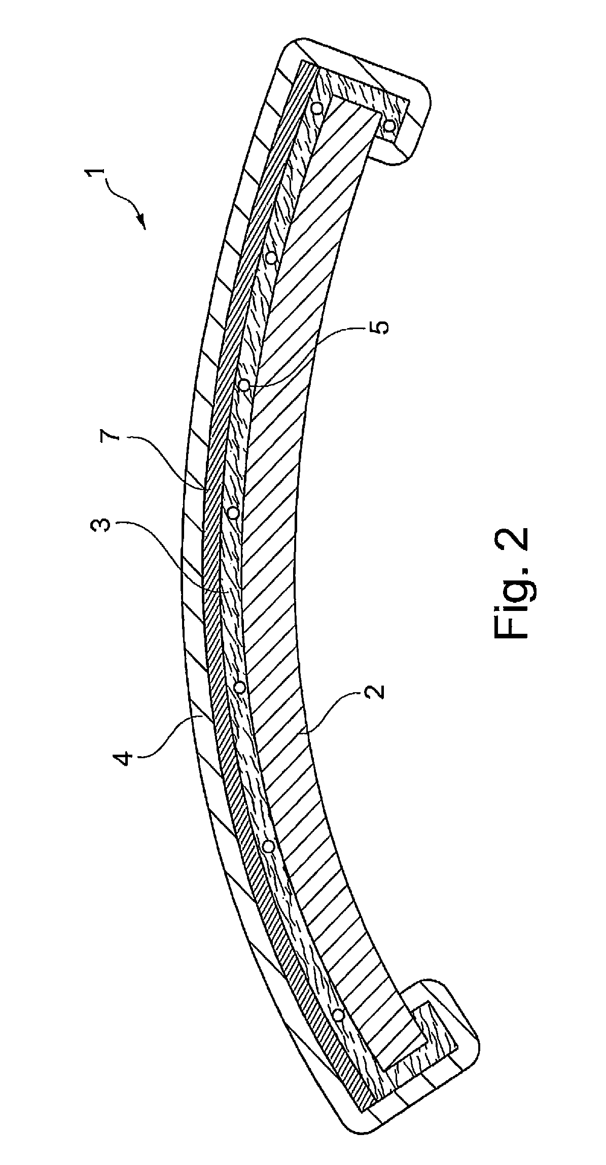
[0032]FIG. 1 is a schematic sectional view of an interior lining 1 in the example of a decorative part in the finished state. The heating layer 3 formed as a non-woven fabric is connected to the upper layer 4 formed of leather to form a layer composite, wherein the connection is formed by lamination of the heating layer onto the upper layer 4. A heating wire 5 extends inside the heating layer 3 and extends substantially over the entire surface area of the carrier 2 formed as a decorative part of a door lining. The layer composite formed of the heating layer 3 and upper layer 4 is press-laminated onto the carrier 2, wherein the heating layer preferably has a thickness of 0.3 to 0.8 mm in the end state. The heating wire 5 has electrical connections (not shown) so as to supply the energy required for heating.

[0033]The upper layer has a perforation 6, illustrated by way of example, so as to accelerate the passage of heat to the vehicle interior. The heat produced at the heating wire 5 i...


PUM

PropertyMeasurementUnit
thicknessaaaaaaaaaa
thicknessaaaaaaaaaa
thicknessaaaaaaaaaa

Abstract

The invention relates to an interior lining for vehicles and aircraft having a carrier and a heating layer and an upper layer, wherein the at least one heating layer is arranged between the carrier and the upper layer, and the heating layer and the upper layer are directly or indirectly interconnected, and to a method for producing such an interior lining, wherein at least one heating layer is pre-laminated onto an upper layer to form a layer composite, and the layer composite is press-laminated, membrane-laminated or vacuum-laminated onto a carrier, or alternatively, in order to produce such an interior lining, a heating layer is pre-laminated onto a carrier to form a carrier / layer composite, and an upper layer is press-laminated, membrane-laminated or vacuum-laminated onto the carrier / layer composite.

Description

CROSS-REFERENCE TO RELATED APPLICATIONS[0001]This application is a US national stage filing under 35 USC §371 of International Patent Application No. PCT / EP2010 / 067242 filed on Nov. 10, 2010, and claims priority under the Paris Convention and 35 USC §119 to German Patent Application No. 10 2009 052 535.1 filed on Nov. 11, 2009.FIELD OF THE DISCLOSURE[0002]The invention relates to an interior lining for vehicles and aircraft, comprising a carrier, at least one heating layer and an upper layer, wherein the at least one heating layer is arranged between the carrier and the upper layer and at least the at least one heating layer and the upper layer are interconnected directly or indirectly. The invention further relates to a method for producing an interior lining of this type, wherein at least one heating layer is pre-laminated onto an upper layer to form a layer composite and the layer composite is press-laminated, membrane-laminated or vacuum-laminated onto a carrier, or alternativel...

Claims


Application Information

Patent Timeline
Patent Type & Authority Patents(United States)
IPC IPC(8): B60H1/22H05B3/28B60H1/00B60R13/02B64C1/40
CPCB60H1/2215B60H1/00271B64C1/40B60R13/02B60H2001/2287B60R2013/0287B60H1/2226B60H1/2227Y10T156/10B60H1/22B60H1/34F25B27/02F24F12/00
Inventor HERMANN, VOLKEREWERT, MICHAEL
Owner NBHX TRIM
Why Eureka
Try Eureka