Microelectromechanical system megasonic transducer

Active Publication Date: 2015-02-17
SILICON LIGHT MACHINES CORP
View PDF10 Cites 42 Cited by
  • Summary
  • Abstract
  • Description
  • Claims
  • Application Information

AI Technical Summary

Problems solved by technology

Unfortunately, the operating frequency or resonant frequency of piezoelectric transducers is determined by a fil...

Method used


Image

  • Microelectromechanical system megasonic transducer
  • Microelectromechanical system megasonic transducer
  • Microelectromechanical system megasonic transducer

Examples


Embodiment Construction

[0029]The present invention is directed to megasonic systems including MicroElectroMechanical System (MEMS) transducers, and to methods of fabricating and using the same.

[0030]A megasonic systems and methods according to the present invention will now be described with reference to FIGS. 1 through 16. For purposes of clarity, many of the details of megasonic systems in general and megasonic cleaning systems in particular that are widely known and are not relevant to the present invention have been omitted from the following description. The drawings described are only schematic and are non-limiting. In the drawings, the size of some of the elements may be exaggerated and not drawn to scale for illustrative purposes. The dimensions and the relative dimensions may not correspond to actual reductions to practice of the invention.

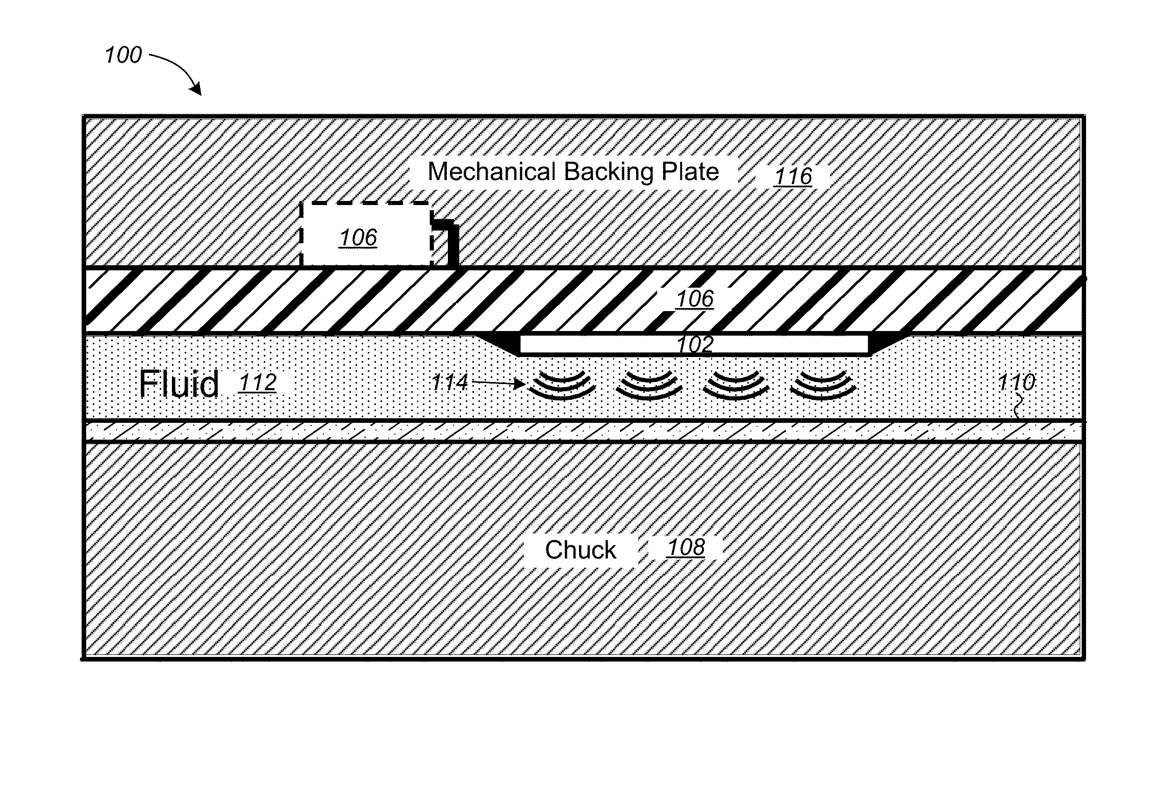
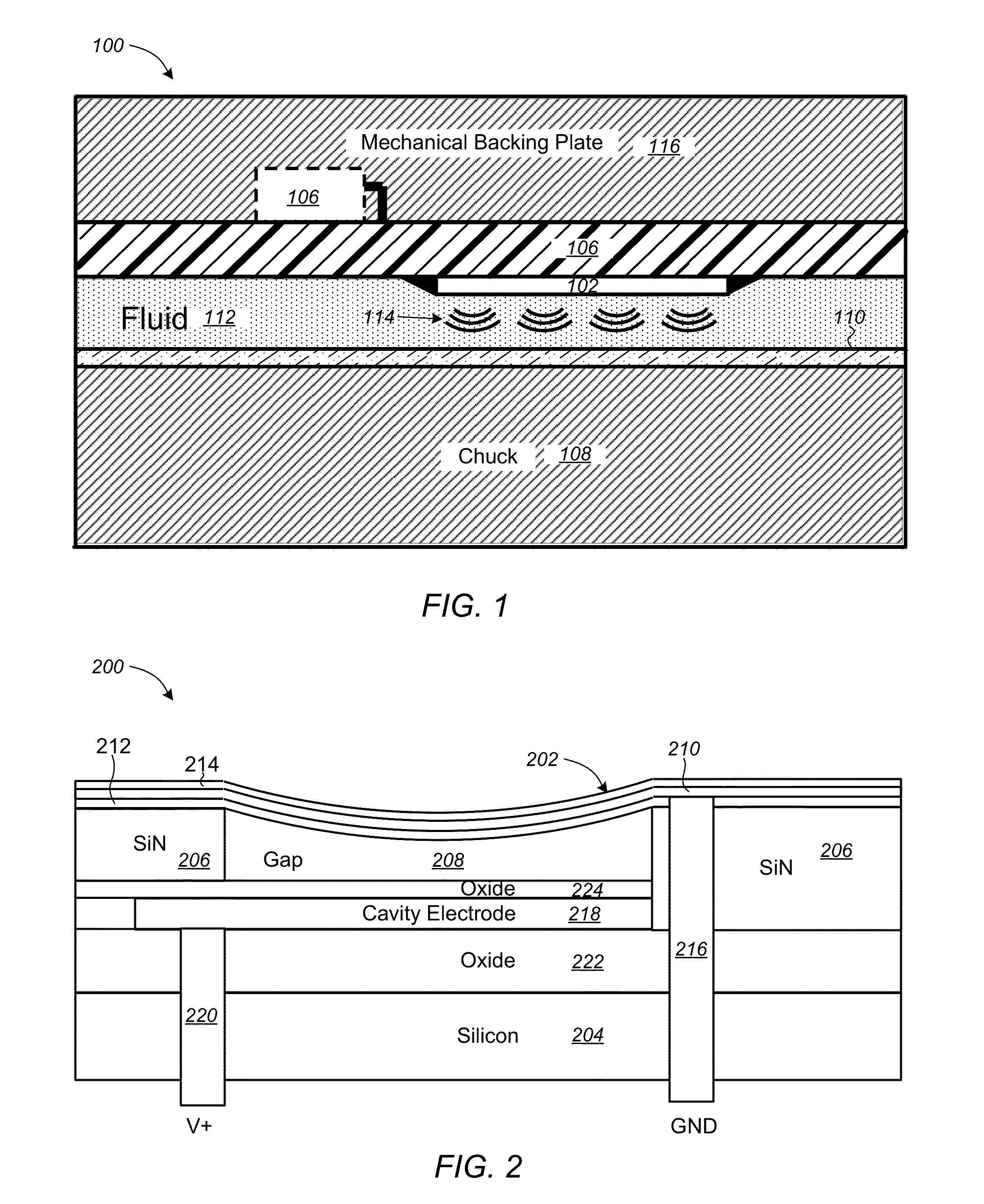
[0031]Referring to FIG. 1, in one exemplary embodiment the megasonic system 100 includes a number of a voltage controlled Micro-Electromechanical System (MEMS)...


PUM

PropertyMeasurementUnit
Fractionaaaaaaaaaa
Thicknessaaaaaaaaaa
Diameteraaaaaaaaaa

Abstract

Megasonic cleaning systems and methods of fabricating and using the same are provided. In one embodiment, the system comprises a plurality of Micro-Electromechanical System (MEMS) transducers, each transducer including a movable membrane with a membrane electrode coupled to a first potential disposed above and spaced apart from an upper surface of a die including a cavity electrode coupled to a second potential, the membrane including multiple layers including a polysilicon layer between a top silicon nitride layer and a bottom silicon nitride layer, and the membrane electrode includes the polysilicon layer; a chuck on which a target workpiece is positioned; and a fluid to couple sonic energy from the plurality of MEMS transducers to the target workpiece. Other embodiments are also provided.

Description

CROSS-REFERENCE TO RELATED APPLICATIONS[0001]The present application claims the benefit of priority under 35 U.S.C. 119(e) to U.S. Provisional Patent Application Ser. No. 61 / 359,519 entitled “Microelectromechanical System Megasonic Transducer,” filed Jun. 29, 2010, which application is hereby incorporated by reference in its entirety.TECHNICAL FIELD[0002]The present invention relates generally to sonic transducers, and more particularly to megasonic systems including MicroElectroMechanical System (MEMS) transducers and to methods of fabricating and using the same.BACKGROUND[0003]Sonic transducers are widely used for a number of applications including medical imaging, cleaning systems or scrubbers used in fabricating semiconductor or Micro-Electromechanical System (MEMS) devices. In a typical cleaning system substrates, such as silicon wafers, are immersed in a liquid to which sonic energy is applied. High intensity sound waves generate pressure fluctuations that lead to cavitation, ...

Claims


Application Information

Patent Timeline
IPC IPC(8): H02N2/00B08B3/12
CPCB08B3/12B06B1/0292
Inventor HIROE, TOSHIOHAROLD, ZAREMPAYNE, ALEXANDERHUNTER, JAMES
Owner SILICON LIGHT MACHINES CORP
Why Eureka
Try Eureka