Position tracking system and method using radio signals and inertial sensing

a technology of positioning tracking and radio signals, applied in direction finders, navigation instruments, instruments, etc., can solve the problems of gps positioning devices, affecting and requiring an unobstructed view of the sky, so as to improve the stability of mobile devices' rf signals and improve the stability of position solutions

Active Publication Date: 2015-02-17
POSITION IMAGING
View PDF41 Cites 99 Cited by
  • Summary
  • Abstract
  • Description
  • Claims
  • Application Information

AI Technical Summary

Benefits of technology

[0013]No examples exist of RF-based position tracking systems that use inertial devices in a tracked mobile device to increase stability of the mobile device's RF signals received at the system's antennae. Therefore, what is needed is an RF position tracking system that tracks the position of one or more wireless mobile devices in two or three dimensions, improves on the limitations of GPS systems, and effectively integrates inertial sensing information in a combined system that allows the user to obtain a more stabilized and accurate position solution.

Problems solved by technology

One limitation of GPS receivers is that they require an unobstructed view of the sky.
A further limitation of GPS location devices is their dependence on an accurate external time reference.
More receiver antennae provide better coverage and more accuracy, but do so with increased complexity and cost.
The major source of error in RF positioning systems is signal propagation errors, such as multipath.
While many methods have attempted to mitigate this problem (antennae diversity, spread spectrum), signal propagation errors are very difficult to totally eliminate.
A sourceless navigation system does not have these issues, but does have its own set of problems.
Unfortunately, commercial, low-cost devices have drift, bias and scale factor errors and orientation motion and positional motion need to be algorithmically separated.
A relatively small offset error on the gyroscope signal will introduce large integration errors.
No examples exist of RF-based position tracking systems that use inertial devices in a tracked mobile device to increase stability of the mobile device's RF signals received at the system's antennae.

Method used


Image

  • Position tracking system and method using radio signals and inertial sensing
  • Position tracking system and method using radio signals and inertial sensing
  • Position tracking system and method using radio signals and inertial sensing

Examples


second embodiment

[0059]FIG. 3 represents different approaches to the system 1. When interface 36 is not included, the result is a linearized Kalman filtering approach. When it 36 is there, the result is an extended Kalman filter. Linearized Kalman filters are derived assuming a linearization was performed around the operating point of the filter. Extended Kalman filters utilize non-linear models. Both filters have pros and cons, such as implementation simplicity and speed of processing.

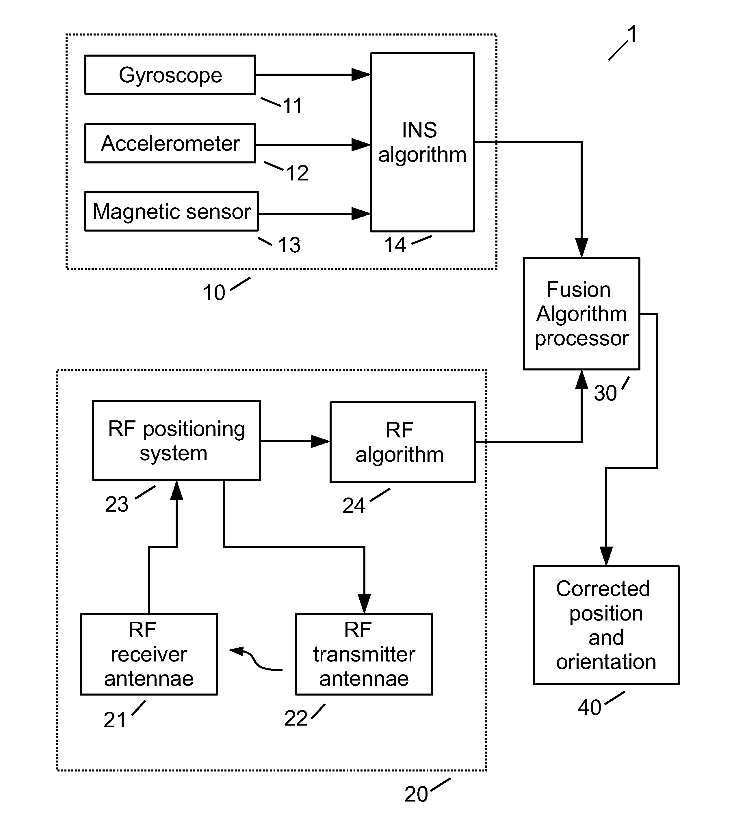
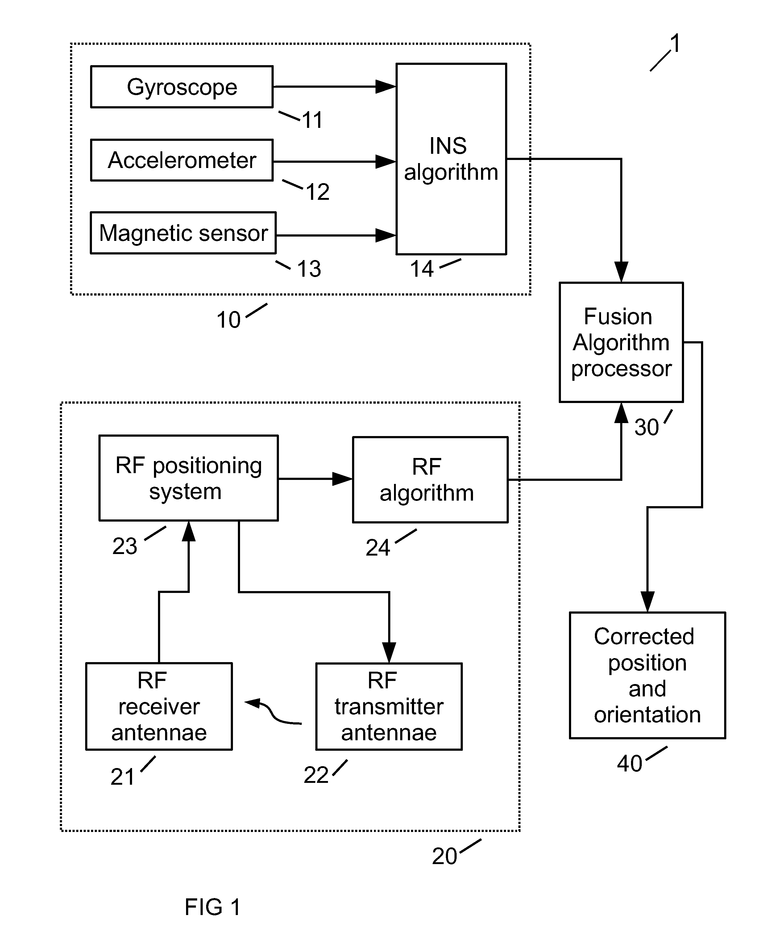
[0060]In this second embodiment, the fusion of RF tracking and inertial tracking is performed in a loosely coupled manner. In loosely-coupled fusion, a link 36 sends the error signal from the Kalman filter 30 is sent to the inertial sensing processor 14 to modify the IMDS 10 output. A feed-forward, complementary filter design, also known as a RF position aided IMDS design, is shown in FIG. 3. Many of the main blocks were already defined in FIG. 1. At the instant at which the GPS measurement is valid, the IMDS state is...

third embodiment

[0062]In a third embodiment shown in FIG. 4, the fusion of RF tracking and inertial tracking is performed in a loosely-coupled manner. As noted above, loosely-coupled fusion is when link 36 sends the error signal from the Kalman filter 30 to the inertial sensing processor 14 to modify the IMDS 10 output. An example of a feed-forward, complementary filter design, also known as a RF range-aided IMDS design, is shown in FIG. 4. Many of the main blocks were already defined in FIGS. 1 and 3. The RF algorithm, however, is now incorporated into Kalman filter 30. Transformation block 35 takes the position solution from the IMDS system 10 and converts it back into range data. Range error is determined in block 31 by subtracting this ranged data from that obtained from RF positioning system 23. This error range data output of block 31 is now used by Kalman filter 30 to compute a position or position and orientation error solution, which in turn, is used to correct output 40 via block 32. This...


PUM


Abstract

An RF position tracking system for wirelessly tracking the three dimensional position of a device that transmits a radio signal. The device has an antenna and at least one inertial sensor. The system uses a plurality of receiver antennas to receive the device's radio signal at each antenna. The device also incorporates an inertial sensor to improve position stability by allowing the system to compare position data from radio signals to data provided by the inertial sensor.

Description

[0001]This Patent Application claims the benefit of U.S. Provisional Patent Application No. 61 / 413,026 filed on Nov. 12, 2010, entitled, “POSITION TRACKING SYSTEM AND METHODS USING RADIO SIGNALS AND INERTIAL SENSING,” the contents and teachings of which are hereby incorporated by reference in their entirety.TECHNICAL FIELD[0002]The present disclosure relates generally to position tracking of mobile devices. More particularly, the present disclosure relates to a position tracking system and method using radio signals and inertial sensing.RELATED ART[0003]In a Global Positioning System (GPS), satellites orbiting the earth transmit signals to passive receivers on the ground. The receivers only receive signals, but they do not transmit signals. One limitation of GPS receivers is that they require an unobstructed view of the sky. As a result, GPS receivers typically are better suited for outdoor use and in areas away from tall buildings or heavy tree cover. A further limitation of GPS lo...

Claims


Application Information

Patent Timeline
Patent Type & Authority Patents(United States)
IPC IPC(8): G01S3/02G01S5/04
CPCG01S5/0027G01S5/0036G01S5/0063G01S5/02585G01C21/1654G01S5/0294
Inventor HILL, EDWARDSCHNEIDER, MARK
Owner POSITION IMAGING
Why Eureka
Try Eureka