Thermoelectric generation for a gas turbine
a technology of gas turbine and thermal energy, applied in the direction of machines/engines, lighting and heating equipment, energy-saving board measures, etc., to achieve the effect of improving efficiency
- Summary
- Abstract
- Description
- Claims
- Application Information
AI Technical Summary
Benefits of technology
Problems solved by technology
Method used
Image
Examples
first embodiment
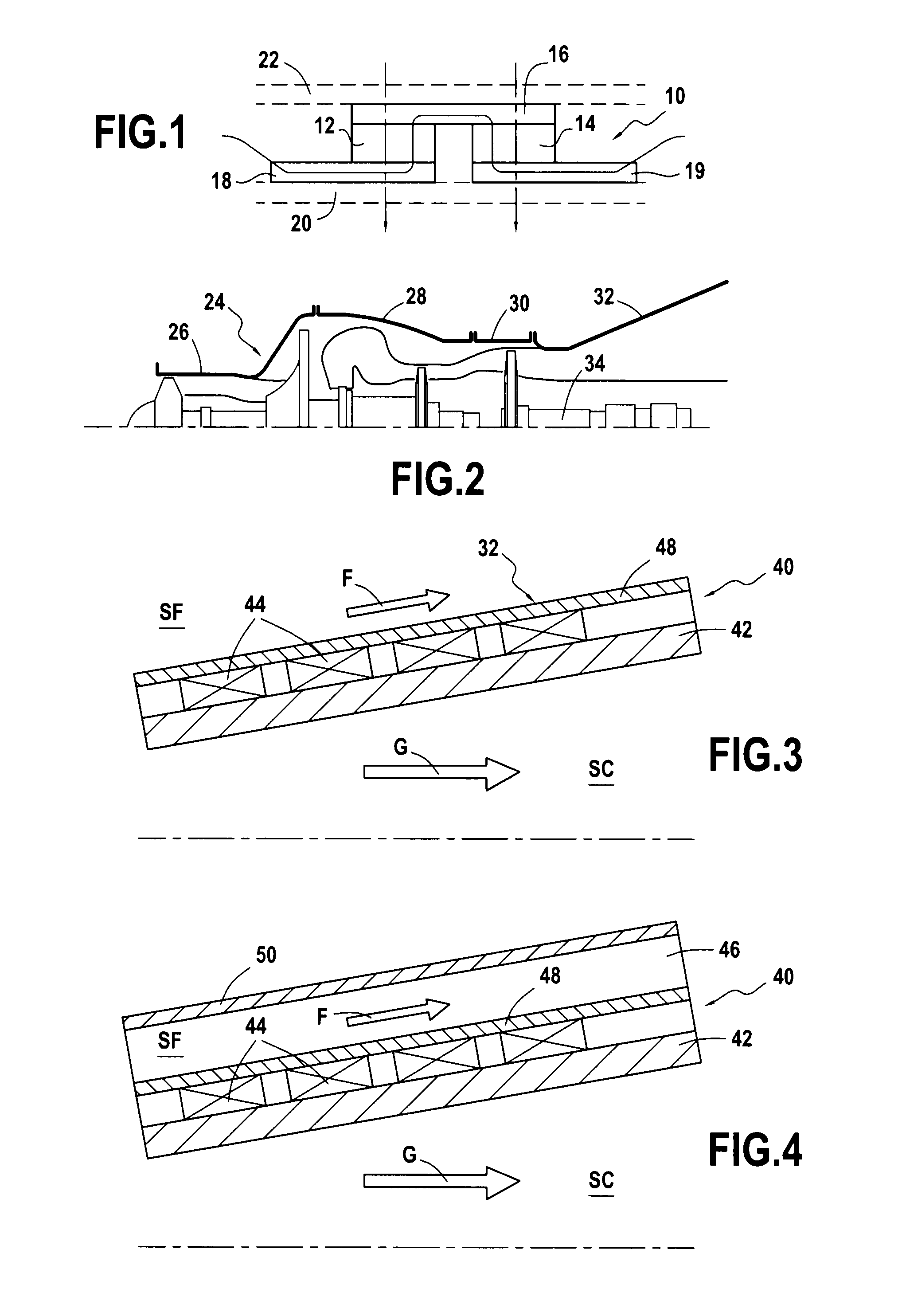
[0031]In the first embodiment shown in FIG. 3, the electrical power production device 40 is mounted directly on the outside wall 42 of the nozzle 32. The electrical power generation device 40 is preferably constituted by sets of thermoelectric cells that are associated with one another to form annular assemblies 44 that are distributed regularly along the length of the wall 42 of the nozzle 32. Each annular ring is naturally constituted by a sequence of thermoelectric cells of the type shown in FIG. 1 that are interconnected electrically and in which the mechanical supports 22 and 20 are flexible so as to be able to fit together over the surface of revolution formed by the wall 42 of the nozzle 32. Thus, the first face of the thermoelectric conversion elements 44 is in contact via a heat bridge with the outside face of the wall 42 of the nozzle 32, while the second face of the thermoelectric conversion elements 44 is in contact with the outside air that thus acts as a cold source SF...
third embodiment
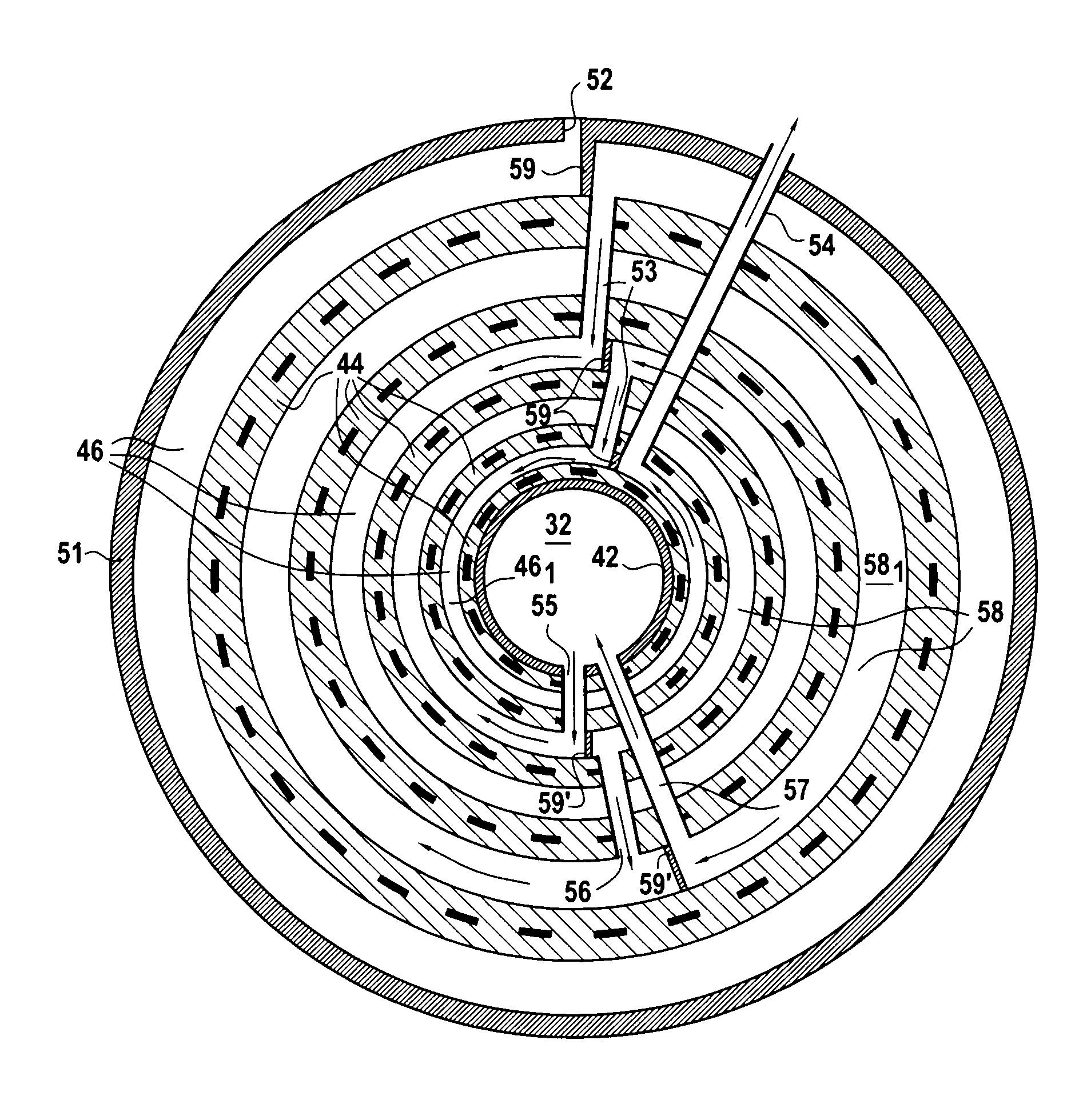
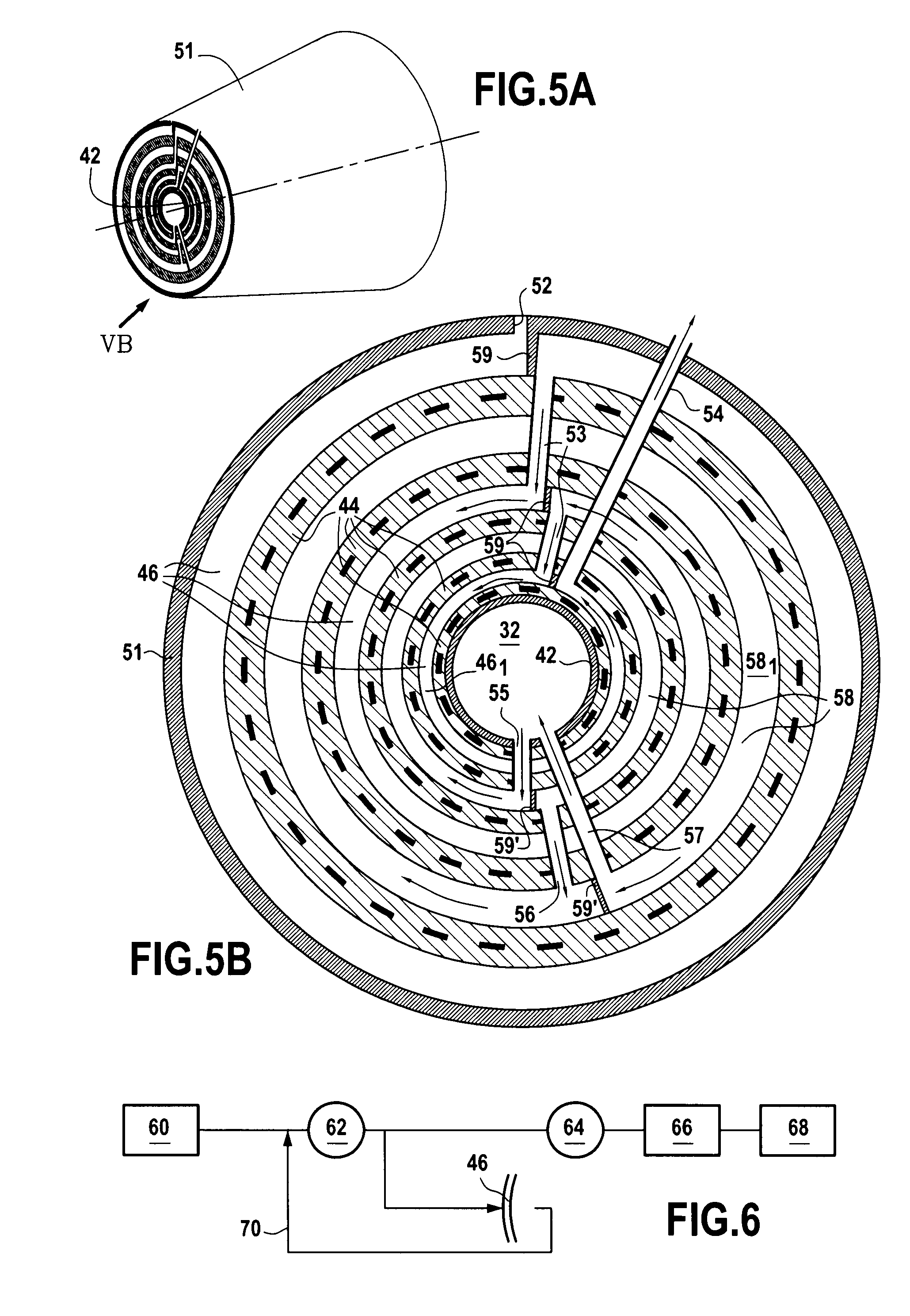
[0033]FIGS. 5A and 5B show the electrical power production device.
[0034]In these figures, there can be seen the wall 42 of the nozzle 32 that acts as the inside wall, and the wall 51 that is the outside wall of the nozzle 32. The cold fluid F (cold air, cooling oil, or fuel) arrives via the inlet tube(s) 52 and then flows (in the direction defined as positive by convention) in the concentric annular zones 46 while describing a spiral movement towards the center of the nozzle. Leaktight radial partitions 59 are arranged in such a manner as to direct the cold fluid F so that it follows said spiral movement in association with tubes 53 providing communication between the annular zones 46. In the last annular zone (smallest radius) 461, the cold fluid F is exhausted to the outside through the tube(s) 54.
[0035]The hot fluid G (nozzle exhaust gas) is taken from the nozzle exhaust gas by the inlet tube(s) 55 and then flows (in the direction defined as negative by convention) in the annular...
PUM
 Abstract
Description
Claims
Application Information
 - R&D
- Intellectual Property
- Life Sciences
- Materials
- Tech Scout
- Unparalleled Data Quality
- Higher Quality Content
- 60% Fewer Hallucinations
Browse by: Latest US Patents, China's latest patents, Technical Efficacy Thesaurus, Application Domain, Technology Topic, Popular Technical Reports.
© 2025 PatSnap. All rights reserved.Legal|Privacy policy|Modern Slavery Act Transparency Statement|Sitemap|About US| Contact US: help@patsnap.com


