Proximal humerus fracture repair plate and system

a proximal humerus and repair plate technology, applied in the field of proximal humerus fracture repair plate and system, can solve the problems of failure of fracture fixation, large and lesser tuberosities are often not amenable to screw fixation, etc., and achieve the effect of increasing the propensity

Inactive Publication Date: 2015-03-03
SHOULDER OPTIONS
View PDF6 Cites 8 Cited by
  • Summary
  • Abstract
  • Description
  • Claims
  • Application Information

AI Technical Summary

Benefits of technology

[0014]While the contour of the fracture repair plate approximates the contour of the lateral aspect of the proximal humerus, the fracture repair plate is configured having a bearing surface configured to minimize plate-to-bone contact upon which the fracture repair plate rests against the bone, thereby substantially reducing the surface area of contact of the inner face of the fracture repair plate and the surface of the bone.
[0015]It is believed that bone health is improved by avoiding compression of the periosteal tissue by minimizing actual surface area of contact of the inner face of the fracture repair plate and the surface of the bone. This is achieved by purposefully mismatching the radius of curvature of the concave surface of the plate relative to the radius of curvature of the bone.
[0018]The present invention is also directed to an anchor and an anchoring system for anchoring a fracture repair plate against a long bone. The preferred anchor includes a shaft portion having a plurality of annular grooves formed about a periphery of the shaft and one or more longitudinal grooves that are formed parallel to a primary axis of the shaft. The anchor also includes a head having an external thread adapted to cooperate with the interior thread formed in an anchor aperture. The anchor is pressed into a hole drilled into the bone such that a “press” or “interference” fit exists between the anchor and the drilled hole. The external thread of the head engages the threads of the anchor aperture and the anchor is tightened and locked to the plate. The annular grooves formed about a periphery of the shaft of the anchor and the longitudinal grooves provide several advantages. First when inserting or withdrawing the anchor from a freshly drilled hole, the longitudinal grooves in particular provide venting for fluid captured in the hole. Additionally as the fracture and the site of insertion of the anchors heal growth of new bone will form in the annular and longitudinal grooves resisting and reducing the possibility of both rotation and pullout of the anchors.
[0021]The present invention is also directed to a fracture repair plate that is further configured having a plurality of suture apertures that provide anchoring for sutures that may be employed in a procedure to reduce a fracture of the head of a long bone. An upper peripheral edge of fracture repair plate is configured having an undercut land. One or more suture apertures are formed along an upper peripheral edge of the fracture repair plate through the undercut land. In one embodiment, the suture apertures exhibit an elongated configuration. The undercut peripheral edge of the fracture repair plate contributes to the ease and accommodation of passing a needle and suture through the plate.

Problems solved by technology

However, the greater and lesser tuberosities are often not amenable to screw fixation due to the frailty of these bony fragments.
In addition, screws tips may cut through the bone, leading to failure of fracture fixation.
Additionally, in the case of comminuted fractures the smaller fragments and their soft tissue connections are not amenable to fixation with screws, but may be more effectively repaired using sutures.

Method used


Image

  • Proximal humerus fracture repair plate and system
  • Proximal humerus fracture repair plate and system
  • Proximal humerus fracture repair plate and system

Examples


Embodiment Construction

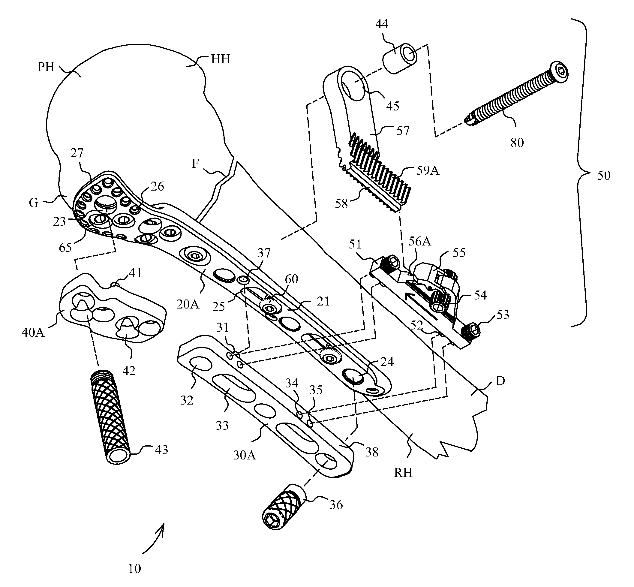
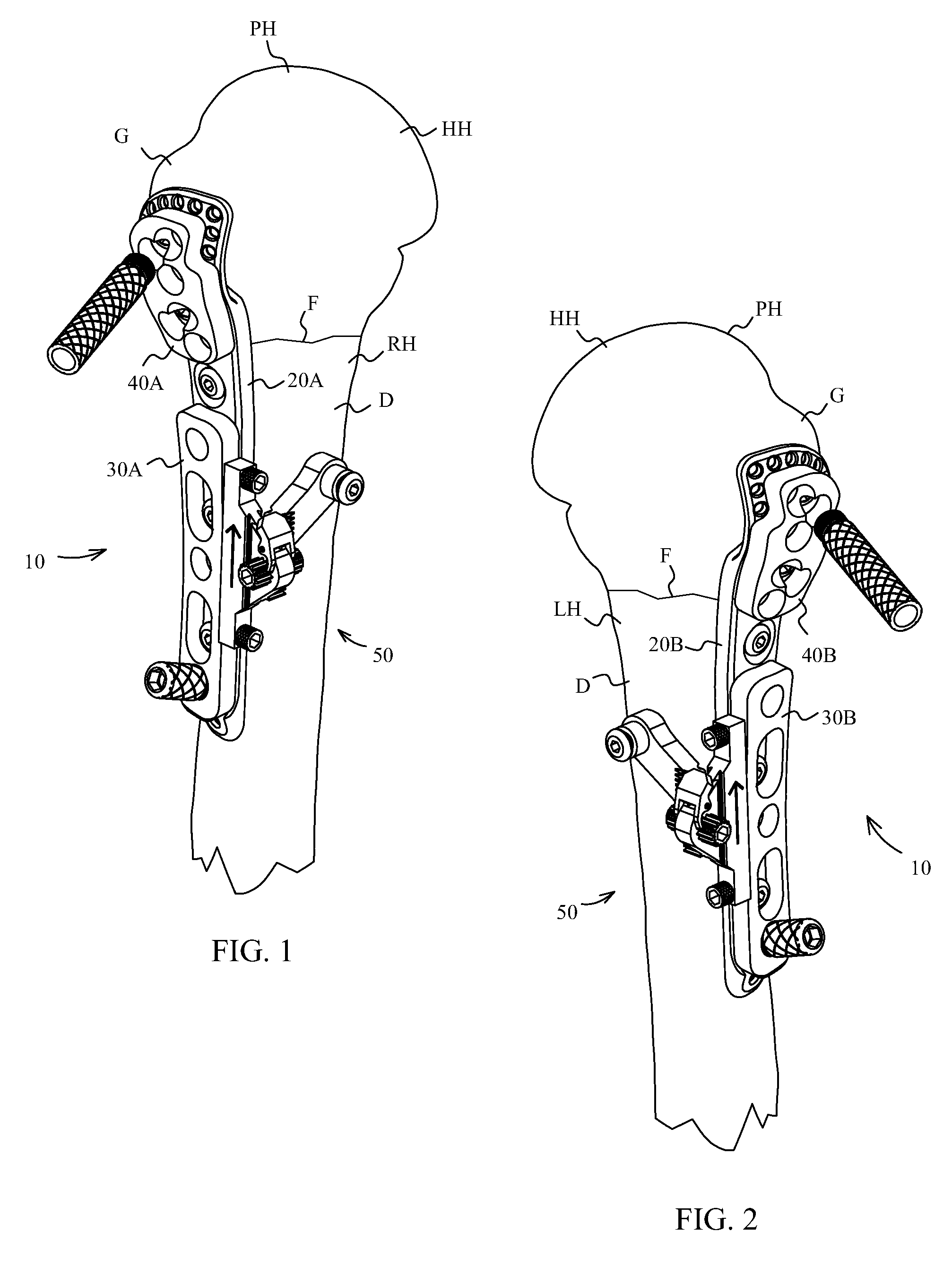
[0034]Referring to FIG. 1, proximal humerus fracture repair system 10 is shown including fracture repair plate 20A attached to a right humerus bone RH including diaphysis D and proximal humerus PH. Proximal humerus PH is shown including humeral head HH and greater turbercle G. Fracture F is a fracture at the surgical neck of the humerus. FIG. 1 shows proximal humerus fracture repair system 10 including first and second right drill guide plates 30A and 40A respectively fixed to outer face 21 of fracture repair plate 20A. Fracture repair plate 20A is specifically adapted for reduction and fixation of a fracture of the right humerus bone RH as seen in FIG. 1. FIG. 2 shows proximal humerus fracture repair system 10 including first and second left drill guide plates 30B and 40B respectively fixed to outer face 21 of fracture repair plate 20B. Reduction mechanism 50 is configured so that it may be adapted for attachment to first right drill guide plate 30A for reduction and fixation of a ...


PUM


Abstract

Devices and systems for repairing bone fractures and more specifically a fracture repair plate that provides for fixation of a metaphysis to the diaphysis of a long bone, for instance a fracture between the proximal humerus and the diaphysis of the humerus. The fracture repair system includes an implantable repair fracture repair plate and a bone anchor for fixing the fracture repair plate to a bone. In one embodiment, the fracture repair plate may also be adapted to serve as an anchor for a suture. The fracture repair system may also include a fracture reduction mechanism attachable to the fracture repair plate for imparting a controlled translational movement between two bone segments along a plane that lies substantially parallel to the surface of the bone to which the fracture repair plate is attached and substantially parallel to the longitudinal axis of the bone shaft.

Description

RELATED APPLICATIONS[0001]This application is a continuation of application Ser. No. 13 / 041,350 entitled Proximal Humerus Fracture Repair Plate and System. Filed Mar. 4, 2011, which claims the benefit of the filing date of a prior-filed Provisional Application Ser. No. 61 / 312,201 entitled Long Bone Head Fracture Repair Plate, filed Mar. 9, 2010, each of which is incorporated herein by reference.FIELD OF THE INVENTION[0002]The present invention relates to a device and system for repairing a fracture of a long bone and more specifically to a fracture repair plate and system that provides for reduction and fixation of a fracture of the humerus bone, for instance a fracture at the surgical neck of the humerus.BACKGROUND[0003]A fracture repair plate is fastenable to the surface of a bone at the site of a fracture to aid in a repair of the fracture by stabilizing the fracture. Attaching a fracture repair plate for such a purpose with threaded bone screws is well known in the art. As the p...

Claims


Application Information

Patent Timeline
Patent Type & Authority Patents(United States)
IPC IPC(8): A61B17/80A61B17/17A61B17/86
CPCA61B17/8057A61B17/1728A61B17/8061A61B17/8004A61B17/864A61B2017/1778A61B17/1778
Inventor HUMPHREY, C. SCOTT
Owner SHOULDER OPTIONS
Why Eureka
Try Eureka