Object exchange method, exposure method, carrier system, exposure apparatus, and device manufacturing method
a technology of carrier system and exposure method, which is applied in the direction of photomechanical equipment, instruments, printers, etc., can solve the problems of high probability of throughput decrement, weaker intensity of 450 mm wafer compared to 300 mm wafer, and difficulty in putting it into practi
- Summary
- Abstract
- Description
- Claims
- Application Information
AI Technical Summary
Benefits of technology
Problems solved by technology
Method used
Image
Examples
first embodiment
A First Embodiment
[0100]A first embodiment of the present invention will be described below, with reference to FIGS. 1 to 22C.
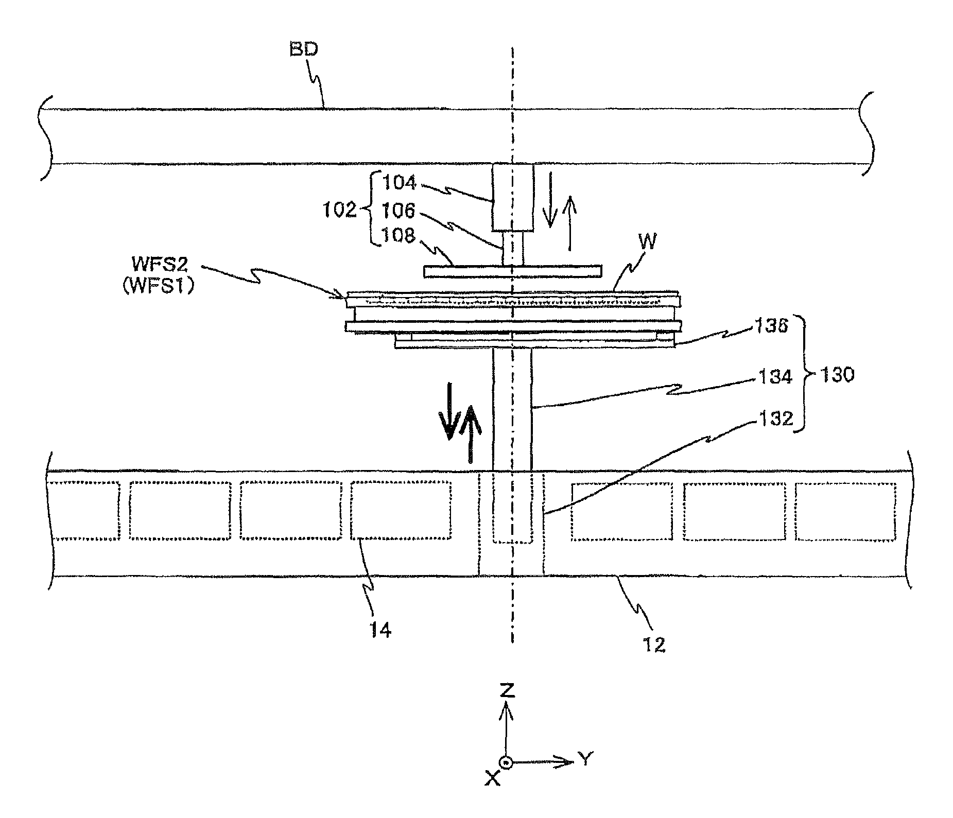
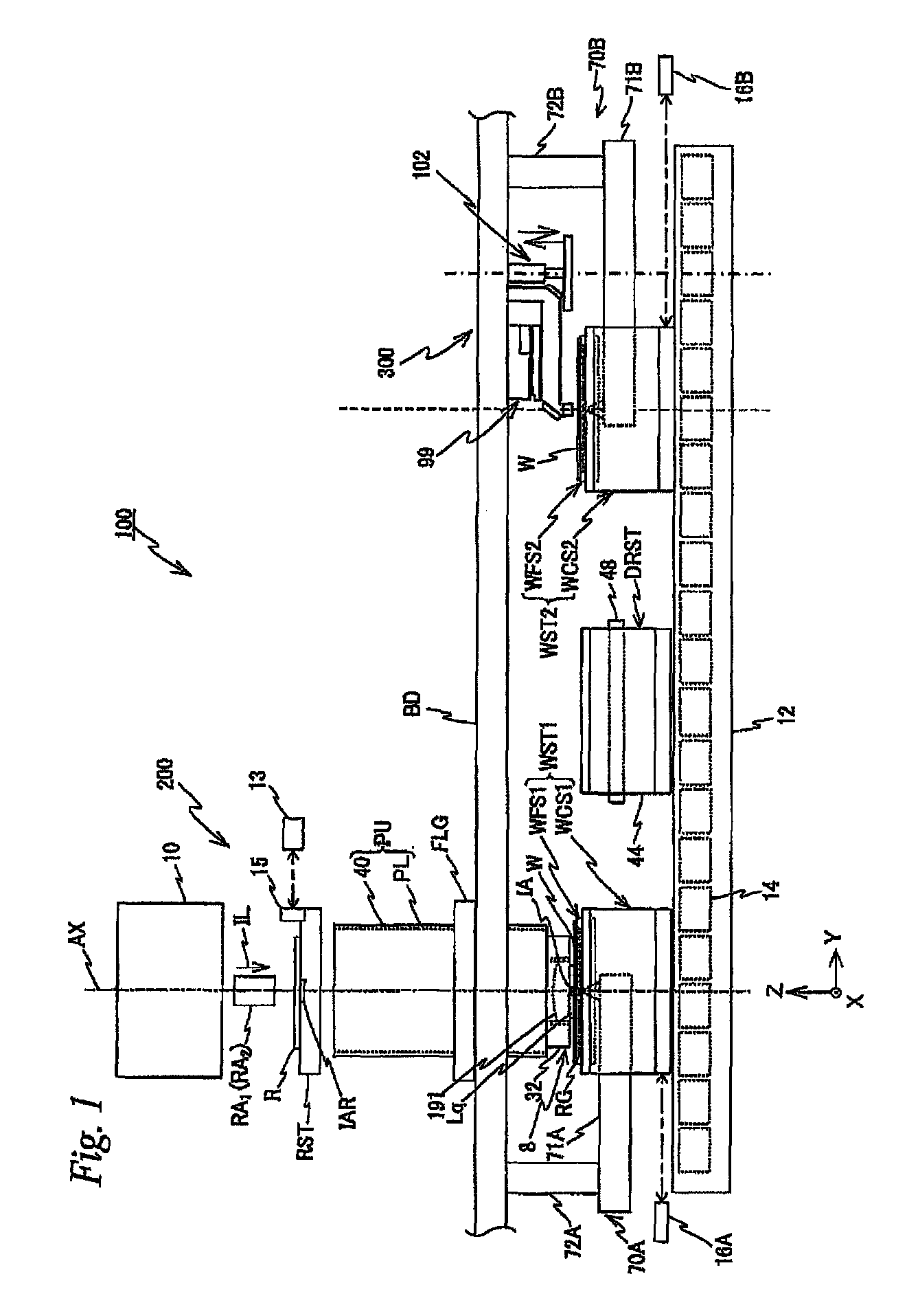
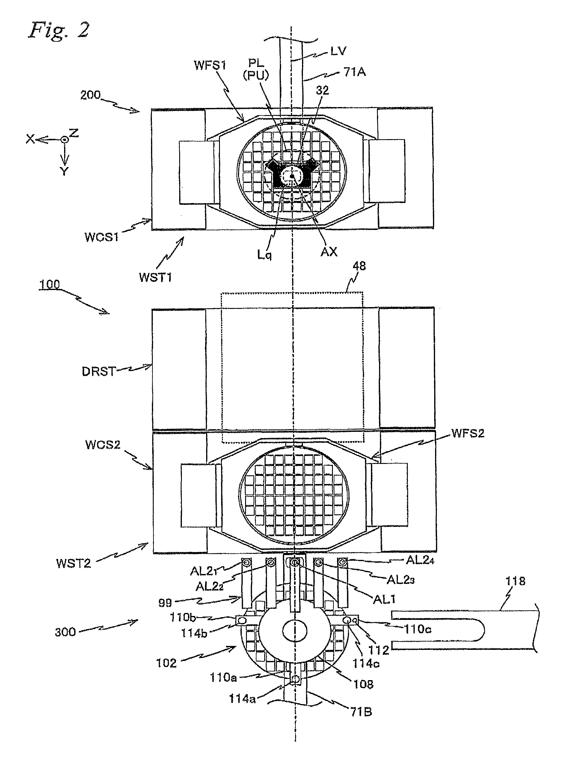
[0101]FIG. 1 schematically shows a configuration of an exposure apparatus 100 in the first embodiment. Exposure apparatus 100 is a projection exposure apparatus by the step-and-scan method, or a so-called scanner. As it will be described later, a projection optical system PL is arranged in the embodiment, and in the description below, a direction parallel to an optical axis AX of this projection optical system PL will be described as the Z-axis direction, a direction within a plane orthogonal to the Z-axis direction in which a reticle and a wafer are relatively scanned will be described as the Y-axis direction, a direction orthogonal to the Z-axis direction and the Y-axis direction will be described as the X-axis direction, and rotational (inclination) directions around the X-axis, the Y-axis, and the Z-axis will be described as θ x, θ y, and θ z directions, ...
second embodiment
A Second Embodiment
[0264]Hereinafter, a second embodiment of the present invention will be described, with reference to FIGS. 25 to 41C. Here, from a viewpoint of avoiding repetition, the same or similar reference numerals will be used for the same or similar sections as in the first embodiment previously described, and a detailed description thereabout will be simplified or omitted.
[0265]FIG. 25 shows a schematic configuration of an exposure apparatus 1000 in the second embodiment when viewed from the +X side, and FIG. 26 shows a partially omitted planar view of exposure apparatus 1000. Further, FIG. 27 shows a center table and the vicinity of a chuck unit which will be described later on. Further, FIG. 28A shows a side view of a wafer stage which exposure apparatus 1000 is equipped with when viewed from the −Y direction, and FIG. 28B shows a planar view of the wafer stage, respectively. FIG. 29A is a planar view of a coarse movement stage, FIG. 29B is a planar view showing a state...
third embodiment
A Third Embodiment
[0314]A third embodiment of the present invention will be described below, with reference to FIGS. 42 to 59. Here, from a viewpoint of avoiding repetition, the same or similar reference numerals will be used for the same or similar sections as in the first and second embodiments previously described, and a detailed description thereabout will be simplified or omitted.
[0315]FIG. 42 shows a schematic configuration of an exposure apparatus 2000 in the third embodiment in a planar view. Exposure apparatus 2000 is a projection exposure apparatus by the step-and-scan method, or a so-called scanner.
[0316]As shown in FIG. 42, exposure apparatus 2000 is equipped with an exposure station 200 in which exposure to wafer W is performed, a measurement station 300 placed away by a predetermined distance to the +Y side of exposure station 200, a center table 130 placed between measurement station 300 and exposure station 200, two wafer stages WST1 and WST2, an unload table 150 pla...
PUM
 Abstract
Description
Claims
Application Information
 - R&D
- Intellectual Property
- Life Sciences
- Materials
- Tech Scout
- Unparalleled Data Quality
- Higher Quality Content
- 60% Fewer Hallucinations
Browse by: Latest US Patents, China's latest patents, Technical Efficacy Thesaurus, Application Domain, Technology Topic, Popular Technical Reports.
© 2025 PatSnap. All rights reserved.Legal|Privacy policy|Modern Slavery Act Transparency Statement|Sitemap|About US| Contact US: help@patsnap.com


