In-situ three-dimensional shape rendering from strain values obtained through optical fiber sensors

a technology of optical fiber sensors and strain values, applied in the direction of instrumentation, testing of fibre optics/optical waveguide devices, structural/machine measurement, etc., can solve the problems of inability or impracticality of direct line-of-sight monitoring, inability to monitor aircraft wing shape in flight, and inability to use direct line-of-sight monitoring

Active Publication Date: 2015-03-03
NASA
View PDF2 Cites 42 Cited by
  • Summary
  • Abstract
  • Description
  • Claims
  • Application Information

AI Technical Summary

Benefits of technology

[0015]It is, therefore, an object of the present invention to provide a new, more accurate meth

Problems solved by technology

There are many different sensors and sensing networks for accomplishing this, but many have inherent limitations that render them unsuitable in certain applications.
This technique requires a clear line of sight, and oftentimes the use of any direct line-of-sight monitoring is either impossible or impractical.
Thus, while suitable as for a controlled testing environment the technique of photogrammetry is impractical to monitor aircraft wing-shape in actual flight due to changes in lighting (night-time versus daytime).
These are costly and impractical, and indeed the wires tend to corrode with age.
There are a number of approaches to the shape measurement problem, but none adequately addresses the requirements of

Method used


Image

  • In-situ three-dimensional shape rendering from strain values obtained through optical fiber sensors
  • In-situ three-dimensional shape rendering from strain values obtained through optical fiber sensors
  • In-situ three-dimensional shape rendering from strain values obtained through optical fiber sensors

Examples


Embodiment Construction

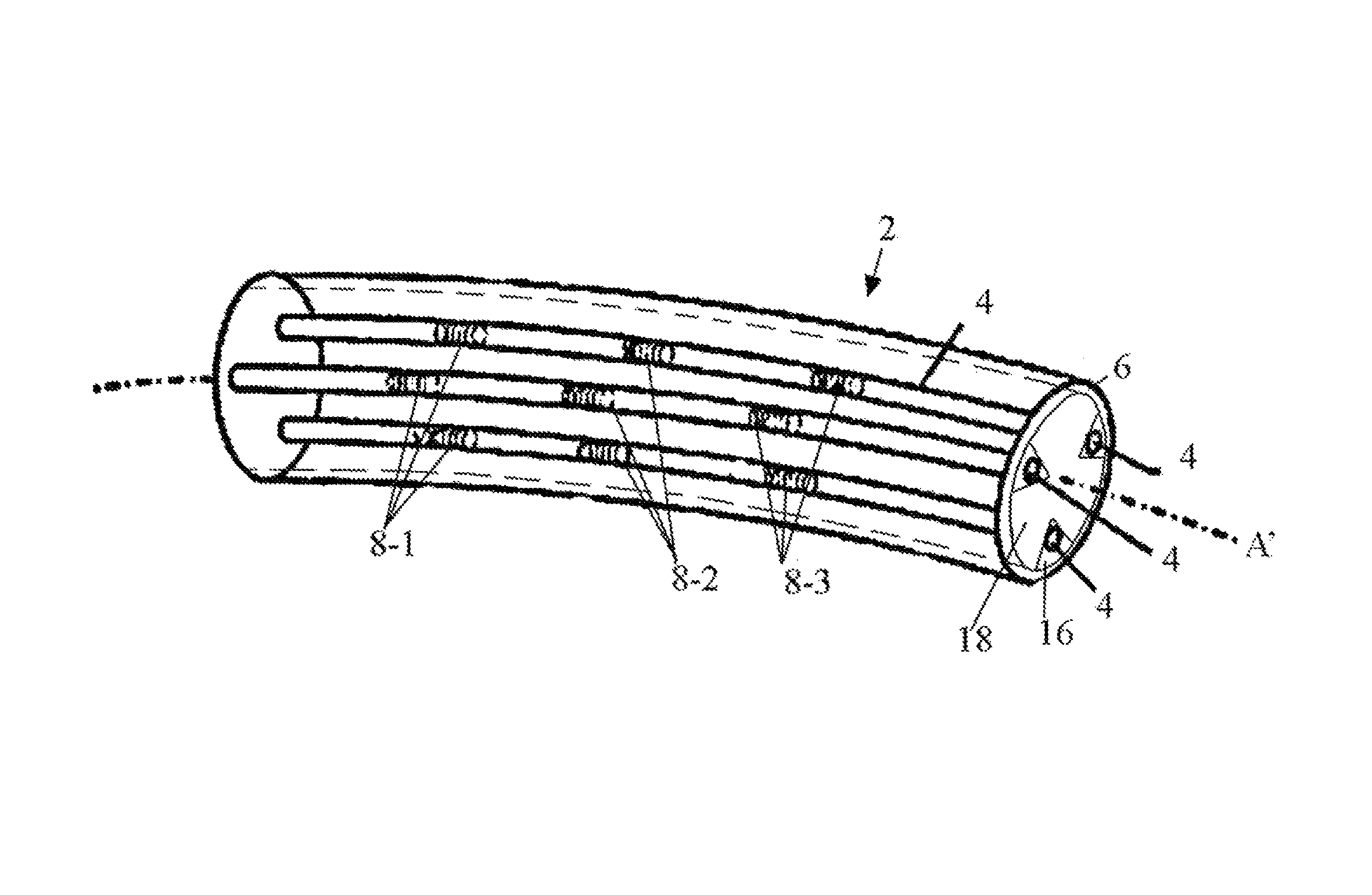
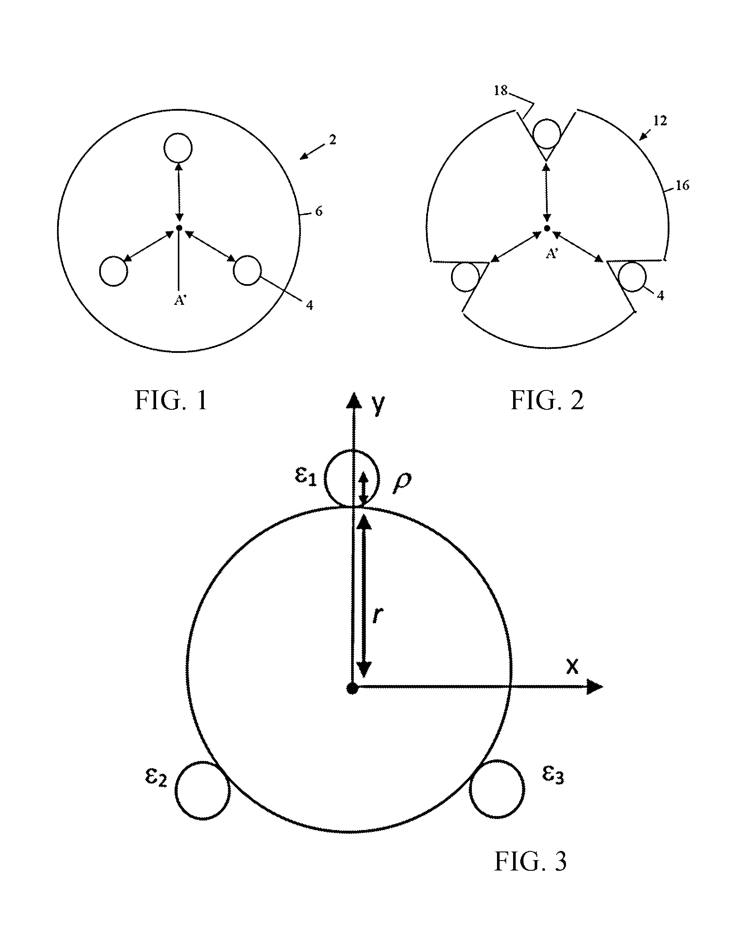
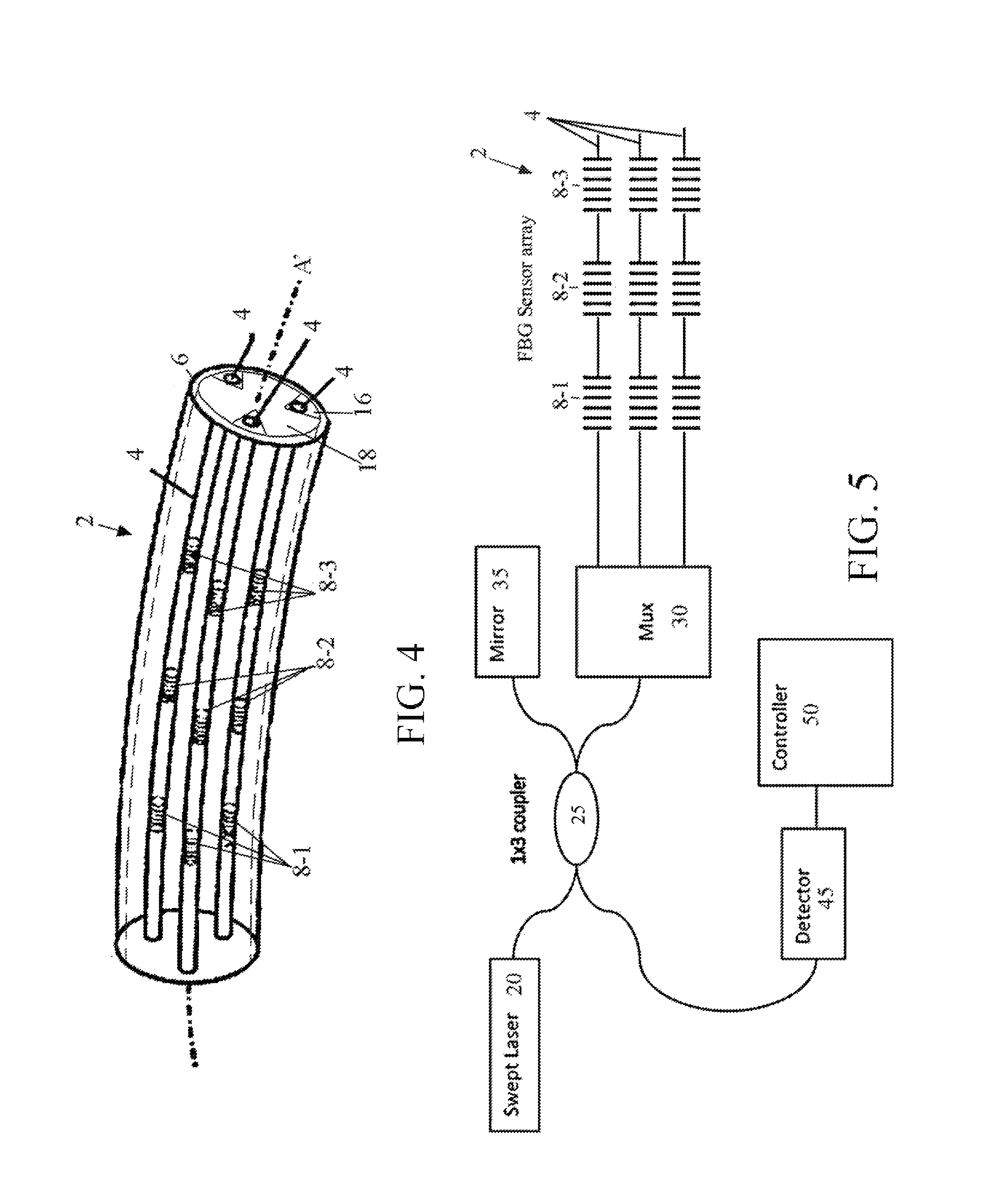
[0032]The present invention is a method and system of rendering the shape of a multi-core optical fiber assembly in three-dimensional Space in real time based on measured fiber strain data. The optical fiber assembly includes three discrete and uniform fiber optic cores run parallel such that they are circularly arrayed at 120° intervals about a central, longitudinal axis. This can be accomplished using a traditional un-bonded multi-core optical fiber. For example, FIG. 1 shows a multi-core optical fiber 2 with three fiber cores 4 arranged in 120 degree separation out a common axis A′ and ceased within a common sheath 6. More preferably, FIG. 2 shows a multi-fiber assembly 12 in which with three discrete uniform optical fiber cores 4 are seated in a plurality of self-centering triangular slots 18 running axially along an elongate elastic body 16. The slots 18 themselves maintain a 120 degree separation about a common axis A′ and provide automatic alignment the optical fibers 4. One ...


PUM


Abstract

A method and system for rendering the shape of a multi-core optical fiber or multi-fiber bundle in three-dimensional space in real time based on measured fiber strain data. Three optical fiber cores arc arranged in parallel at 120° intervals about a central axis. A series of longitudinally co-located strain sensor triplets, typically fiber Bragg gratings, are positioned along the length of each fiber at known intervals. A tunable laser interrogates the sensors to detect strain on the fiber cores. Software determines the strain magnitude (ΔL/L) for each fiber at a given triplet, but then applies beam theory to calculate curvature, beading angle and torsion of the fiber bundle, and from there it determines the shape of the fiber in s Cartesian coordinate system by solving a series of ordinary differential equations expanded from the Frenet-Serrat equations. This approach eliminates the need for computationally time-intensive curve-tilting and allows the three-dimensional shape of the optical fiber assembly to be displayed in real-time.

Description

[0001]This application, as a divisional therefrom, claims priority to application 13 / 485,187, filed May 5, 2012.CLAIM OF PRIORITY AND STATEMENT OF GOVERNMENT RIGHTS[0002]The invention described herein may be manufactured and used by or for the Government of the United States of America for governmental purposes without payment of any royalties thereon or therefor.BACKGROUND OF THE INVENTION[0003]1. Field of the Invention[0004]The present invention relates to optical fiber sensing systems and. more specifically, to a method and system of rendering the shape of a multi-core optical fiber cr multi-fiber bundle in three-dimensional space in real time based on measured fiber strain data.[0005]2. Description of the Background[0006]There are many diverse engineering applications where determining or monitoring the shape of an article or structure is of paramount importance. The science of determining changes to the material and / or geometric properties of a structure is referred to as Struc...

Claims


Application Information

Patent Timeline
IPC IPC(8): G01B9/02G01M11/00
CPCG01M11/30G01B11/18
Inventor CHAN, HON MANPARKER, JR., ALLEN R.
Owner NASA
Why Eureka
Try Eureka