Fiber optic system for monitoring displacement of a structure using quaternion kinematic shape sensing

a fiber optic system and displacement technology, applied in the direction of force measurement by measuring optical property variation, structural/machine measurement, instruments, etc., can solve the problems of high accuracy strain measurement that is not readily achievable by conventional resistive or optical strain gauges, and the euler approach is heavily dependent on trigonometric functions, so as to eliminate compound errors, low cost, and reliable

Active Publication Date: 2020-04-07
NASA
View PDF12 Cites 5 Cited by
  • Summary
  • Abstract
  • Description
  • Claims
  • Application Information

AI Technical Summary

Benefits of technology

[0021]It is, therefore, an object of the present invention to provide a new, more accurate method and system for fiber-optic sensing shape in two and/or three dimensions using single or multi-core optical fibers.
[0022]It is another object to eliminate the compound errors that are experienced with other measurement methods, even for complex shapes.
[0023]It is still another object of the present invention to provide a method and system for fiber-optic sensing shape in two or three dimensions that is low cost, uses off-the-shelf components and software that can run on standard computing platforms, and which is robust and reliable even in high-temperature and high-pressure environments.
[0024]According to the present invention, the above-described and other objects are accomplished by a method and system for rendering the shape and orientation of a three-dimensional structure that analyzes rotation/orientation in quaternion notation. The proposed system and method keeps track of t

Problems solved by technology

Despite the foregoing a strain-based approach must achieve accuracy to tens of nanostrain (10 parts per billion) levels, and such high accuracy strain measurements are not

Method used


Image

  • Fiber optic system for monitoring displacement of a structure using quaternion kinematic shape sensing
  • Fiber optic system for monitoring displacement of a structure using quaternion kinematic shape sensing
  • Fiber optic system for monitoring displacement of a structure using quaternion kinematic shape sensing

Examples


Embodiment Construction

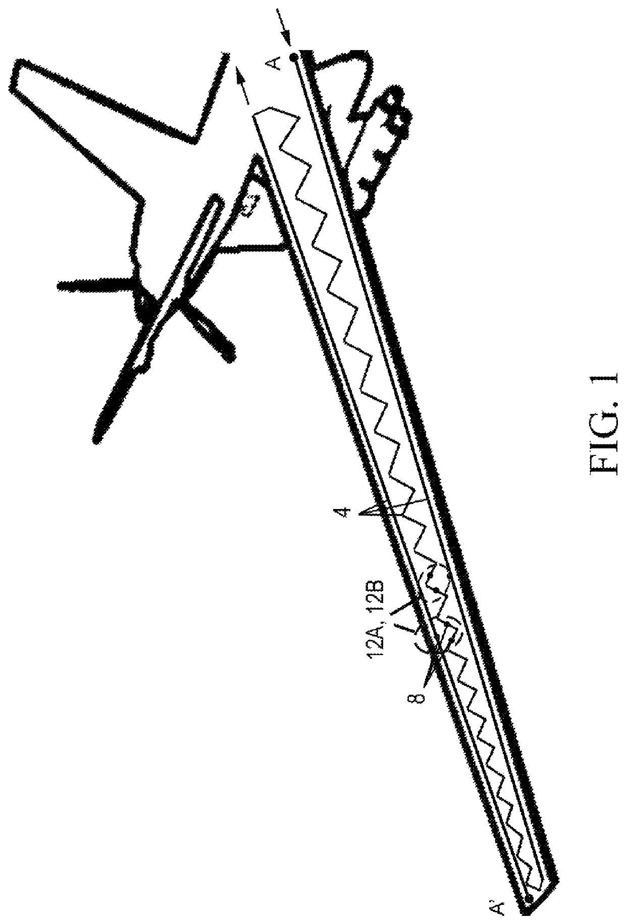
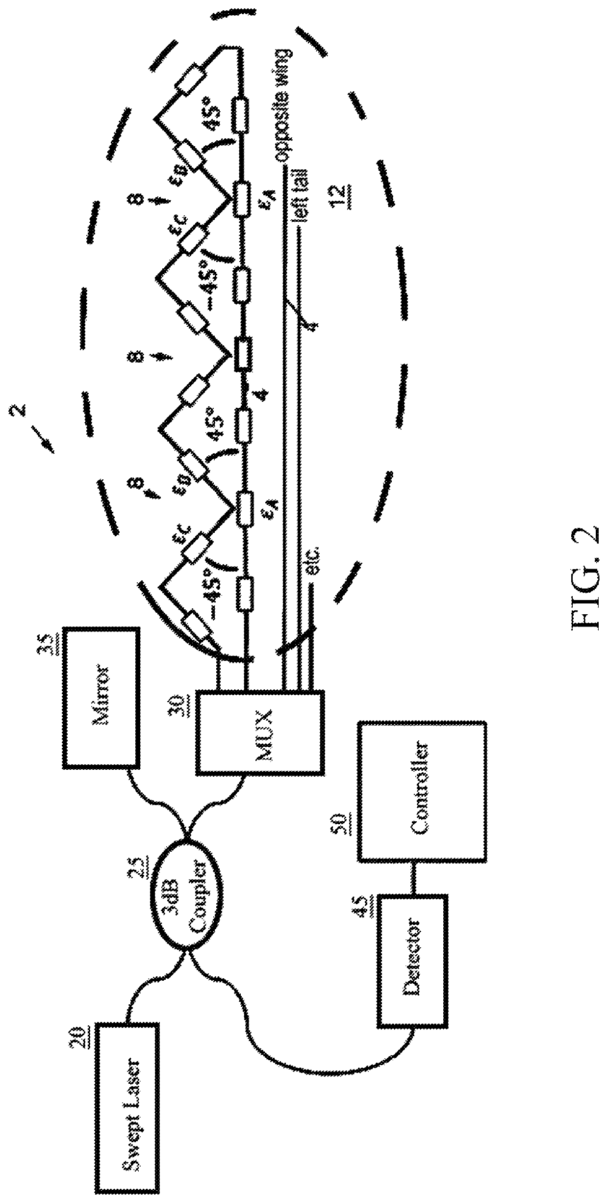
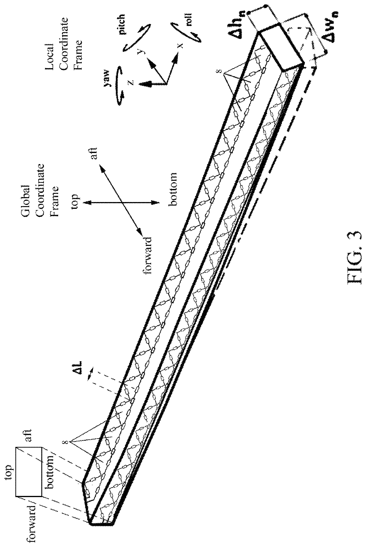
[0030]The present invention is a quaternion-based method and system of rendering the shape of a single or multi-core optical fiber assembly in three-dimensional space in real time based on measured fiber strain data. The optical fiber assembly includes a continuous closed-loop fiber optic core 4 with uniformly-spaced fiber Bragg grating (FBG) sensors 8 arranged in delta-triplets such that the sensors 8 are arrayed at 45° deltas.

[0031]As shown in FIG. 1, the preferred fiber that is used is a single-core optical fiber mounted in a sawtooth configuration in which the single fiber 4 is surface-mounted or embedded along the entire span of the flight control surface (e.g., a wing), running directly end-to-end along the leading edge, doubling back to the near end in a sawtooth pattern that spans the mid-section of the flight control surface, and running directly end-to-end along the trailing edge.

[0032]The fiber optic cores 4 extend entirely across a structure to be monitored such as a win...


PUM


Abstract

A method and system for rendering the quaternion shape and orientation of a three-dimensional structure. The proposed system and method keeps track of twist/roll angles and updates its effect on pitch and yaw orientations. The system relies on a single or multi-core optical fiber or multi-fiber bundle containing fiber Bragg grating sensors (FBGs) arrayed in rosettes at 45° deltas and spaced at uniform intervals along the entire length of the structure to be monitored. A tunable laser is used to interrogate the sensors using optical frequency domain reflectometry (OFDR), which detects shifts in the wavelength reflected by the sensors in response to strain on the fibers. Each sensor is continuously queried by software which determines the strain magnitude (ΔL/L) for each fiber at a given triplet. Given these measured strain values, the software implements a novel quaternion approach to rendering the 3D shape of the fiber including twist.

Description

CROSS-REFERENCE TO RELATED APPLICATIONS[0001]The present application derives priority from U.S. provisional patent application Ser. No. 62 / 555,416 filed on 7 Sep. 2017.STATEMENT OF GOVERNMENT INTEREST[0002]The invention described hereunder was made in the performance of work under a NASA contract, and is subject to the provisions of Public Law #96-517 (35 U.S.C. 202) in which the Contractor has elected not to retain title.BACKGROUND OF THE INVENTION1. Field of the Invention[0003]The present invention relates to optical fiber sensing systems and, more specifically, to a method and system of rendering displacement of shape and / or orientation of a three-dimensional aerospace structure in real time based on measured fiber strain data using quaternion kinematic shape sensing.2. Description of the Background[0004]The ability to determine the displacement of a structure in shape and / or orientation is of great importance to the science of Structural Health Monitoring (SHM). Generally, SHM i...

Claims


Application Information

Patent Timeline
IPC IPC(8): G01B11/16G01L1/24
CPCG01B11/165G01L1/246G01B11/161G01B11/18G01M5/0016G01M5/0041G01M5/0091
Inventor PENA, III, FRANCISCOPARKER, JR., ALLEN R.RICHARDS, WILLIAM LANCECHAN, HON MAN
Owner NASA
Why Eureka
Try Eureka