Optical sensor and electronic apparatus utilizing an angle limiting filter

a technology of angle limitation filter and optical sensor, which is applied in the direction of optical radiation measurement, instruments, spectrometry/spectrophotometry/monochromator, etc., can solve the problems of degrading the controllability of the incidence angle and the inability to acquire desired wavelength resolution, and achieve high precision

Active Publication Date: 2015-03-10
SEIKO EPSON CORP
View PDF18 Cites 35 Cited by
  • Summary
  • Abstract
  • Description
  • Claims
  • Application Information

AI Technical Summary

Benefits of technology

[0008]An advantage of some aspects of the invention is that it provides an optical sensor, an electronic apparatus, and the like capable of controlling an incidence limitation angle of incidence light with high precision.

Problems solved by technology

However, there is a problem in that controllability of the incidence angle is degraded depending on the condition of the width or the height of the opening of the angle limiting filter.
For example, in a spectroscopic sensor, in a case where the angle controllability is degraded, desired wavelength resolution cannot be acquired.

Method used


Image

  • Optical sensor and electronic apparatus utilizing an angle limiting filter
  • Optical sensor and electronic apparatus utilizing an angle limiting filter
  • Optical sensor and electronic apparatus utilizing an angle limiting filter

Examples


Embodiment Construction

[0050]Hereinafter, preferred embodiments of the invention will be described in detail. However, the embodiments described below are not for the purpose of limiting the scope of the invention described in the appended claims, and it cannot be determined that all the configurations described in the embodiments are essential as solving means according to the embodiments of the invention. In addition, although an example will be described below in which the optical sensor is a spectroscopic sensor, the optical sensor according to the embodiments is not limited to a spectroscopic sensor as will be described later.

1. Configuration

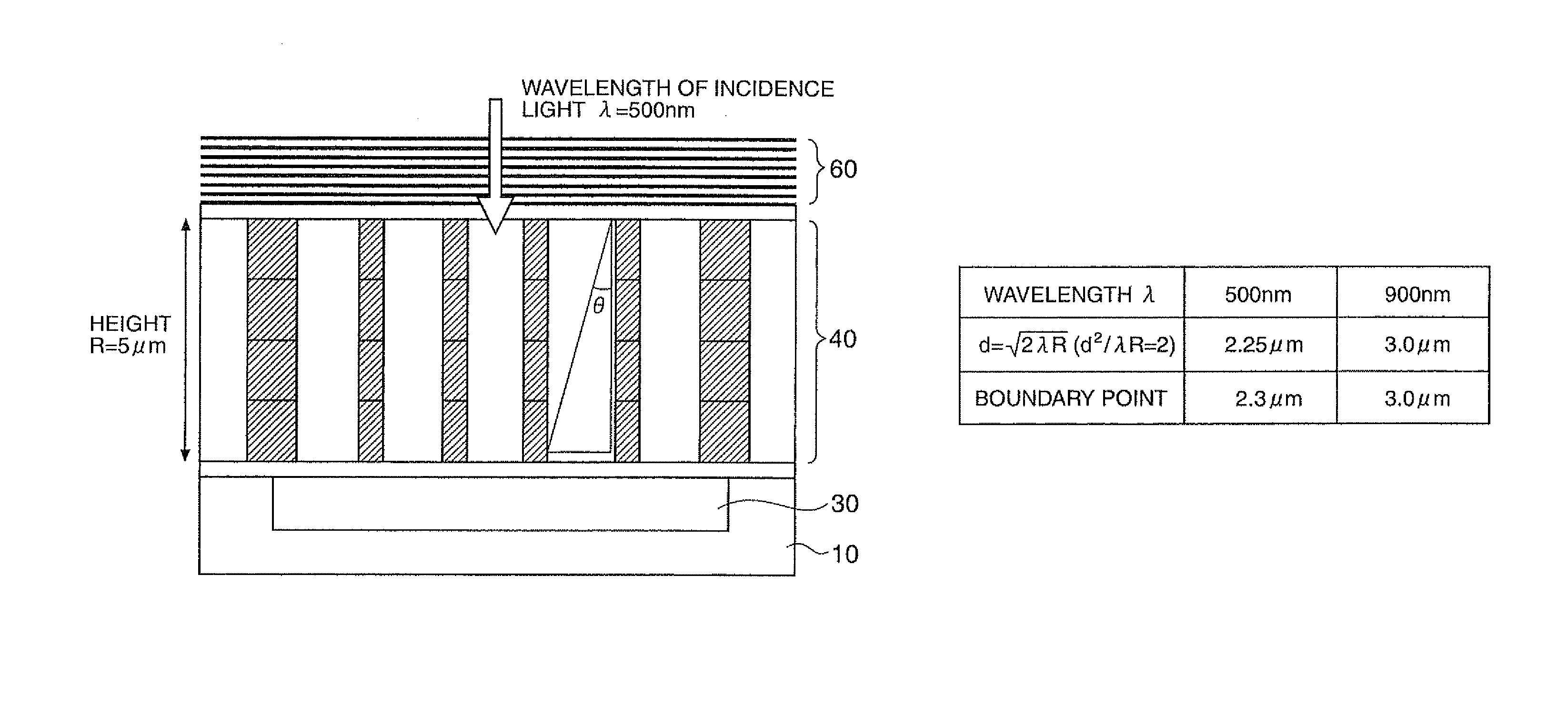
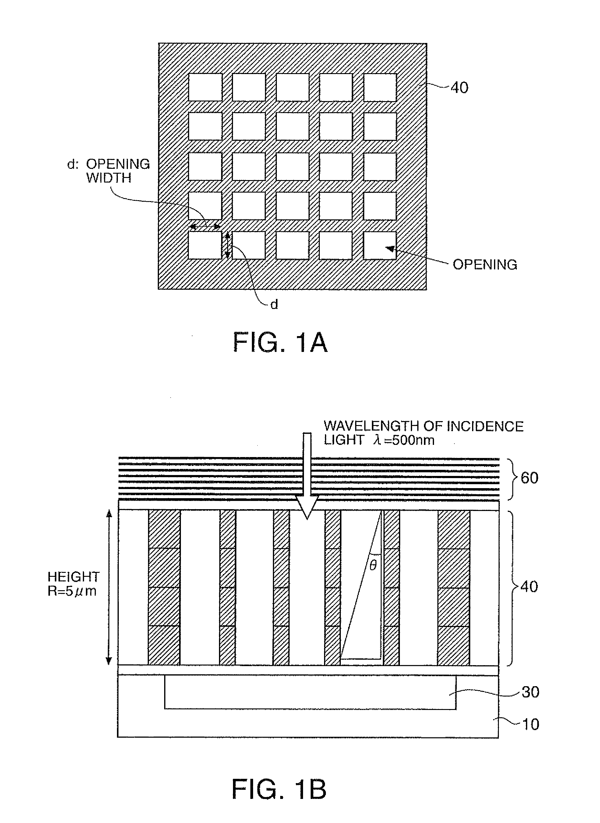
[0051]FIGS. 1A and 1B show a configuration example of a spectroscopic sensor (in a broad sense, an optical sensor) according to this embodiment. Hereinafter, for simplicity, the configuration of this embodiment will be schematically shown, and the dimensions and the ratios illustrated in the figures are not real values.

[0052]FIG. 1A shows a plan view of an angle ...


PUM

PropertyMeasurementUnit
wavelengthaaaaaaaaaa
limitation angleaaaaaaaaaa

Abstract

An optical sensor includes a light receiving element (for example a photodiode) and an angle limiting filter that limits the incidence angle of incidence light with respect to the light receiving area of the light receiving element. When a wavelength of the incidence light is denoted by λ, a height of the angle limiting filter is denoted by R, and a width of an opening of the angle limiting filter is denoted by d, “d2 / λR≧2” is satisfied.

Description

[0001]The entire disclosure of Japanese Patent Application No. 2011-058181, filed Mar. 16, 2011 is expressly incorporated by reference herein.BACKGROUND[0002]1. Technical Field[0003]The present invention relates to an optical sensor, an electronic apparatus, and the like.[0004]2. Related Art[0005]Recently, measurement using an optical sensor has been applied to various fields. For example, in order to diagnose or test target objects, spectroscopic sensors are used. As such spectroscopic sensors, there are pulse oximeters that measure the oxygen saturation in blood by using the light absorption of hemoglobin and saccharimeters that measure the sugar content of a fruit by using light absorption of sugar. In addition, illuminance sensors that are used for measuring illuminance and the like are used.[0006]Among such optical sensors, there are optical sensors that limit the incidence angle of incidence light by using an angle limiting filter (for example, JP-A-6-129908). However, there i...

Claims


Application Information

Patent Timeline
Patent Type & Authority Patents(United States)
IPC IPC(8): G01N21/25G01J1/04G01J1/06G01J3/12G01J3/26G01J3/36G01J3/51
CPCG01J1/06G01J3/26G01J3/36G01J1/0488G01J3/513G01J2003/1213
Inventor UEMATSU, AKIRATERASHIMA, YOSHIYUKISATO, YOICHIMATSUO, ATSUSHI
Owner SEIKO EPSON CORP
Why Eureka
Try Eureka