Glass core planar waveguide laser amplifier

a laser amplifier and glass core technology, applied in the field of optical devices, can solve the problems of large chemical lasers, unsuitable for many applications, and lasers typically limited to a few kilowatts per laser crystal, and achieve the effect of high transparency

Active Publication Date: 2015-03-10
RAYTHEON CO
View PDF18 Cites 19 Cited by
  • Summary
  • Abstract
  • Description
  • Claims
  • Application Information

AI Technical Summary

Problems solved by technology

Unfortunately, chemical lasers are very large and produce toxic byproducts making them unsuitable for many applications.
However, these lasers are typically limited to a few kilowatts per laser crystal due to both the limited size of available crystal materials and the challenges in removing the waste heat form the gain medium.
These limitations have led to approaches to solid-state high-energy lasers (HELs), which require complex arrangements of large numbers of amplifiers in series or series / parallel configurations.
Planar waveguide geometry (PWG) has emerged as a gain medium geometry well-suited suited to extending the output power from a single solid-state laser module to the MW level, but available materials and fabrication processes are a limitation to the ultimate PWG size and output power.
Fabrication of planar waveguides capable of high average power is currently a slow process and has only been scaled to relatively short (approximately 250 mm) lengths due to the lack of growth processes for longer YAG (yttrium-aluminum-garnet) material.
Bulk single crystal materials that are available in larger sizes do not have suitable properties for scaling to high power laser operation.
Ceramic YAG offers long term potential for availability in larger sizes, but scatter and absorption losses in ceramic YAG are still higher than desired and ceramic YAG material is currently limited to about 350 mm in length.
Unfortunately, none of these approaches appears to offer scalability to weapon-class power levels.

Method used


Image

  • Glass core planar waveguide laser amplifier
  • Glass core planar waveguide laser amplifier
  • Glass core planar waveguide laser amplifier

Examples


Embodiment Construction

[0014]Illustrative embodiments and exemplary applications will now be described with reference to the accompanying drawings to disclose the advantageous teachings of the present invention.

[0015]While the present invention is described herein with reference to illustrative embodiments for particular applications, it should be understood that the invention is not limited thereto. Those having ordinary skill in the art and access to the teachings provided herein will recognize additional modifications, applications, and embodiments within the scope thereof and additional fields in which the present invention would be of significant utility.

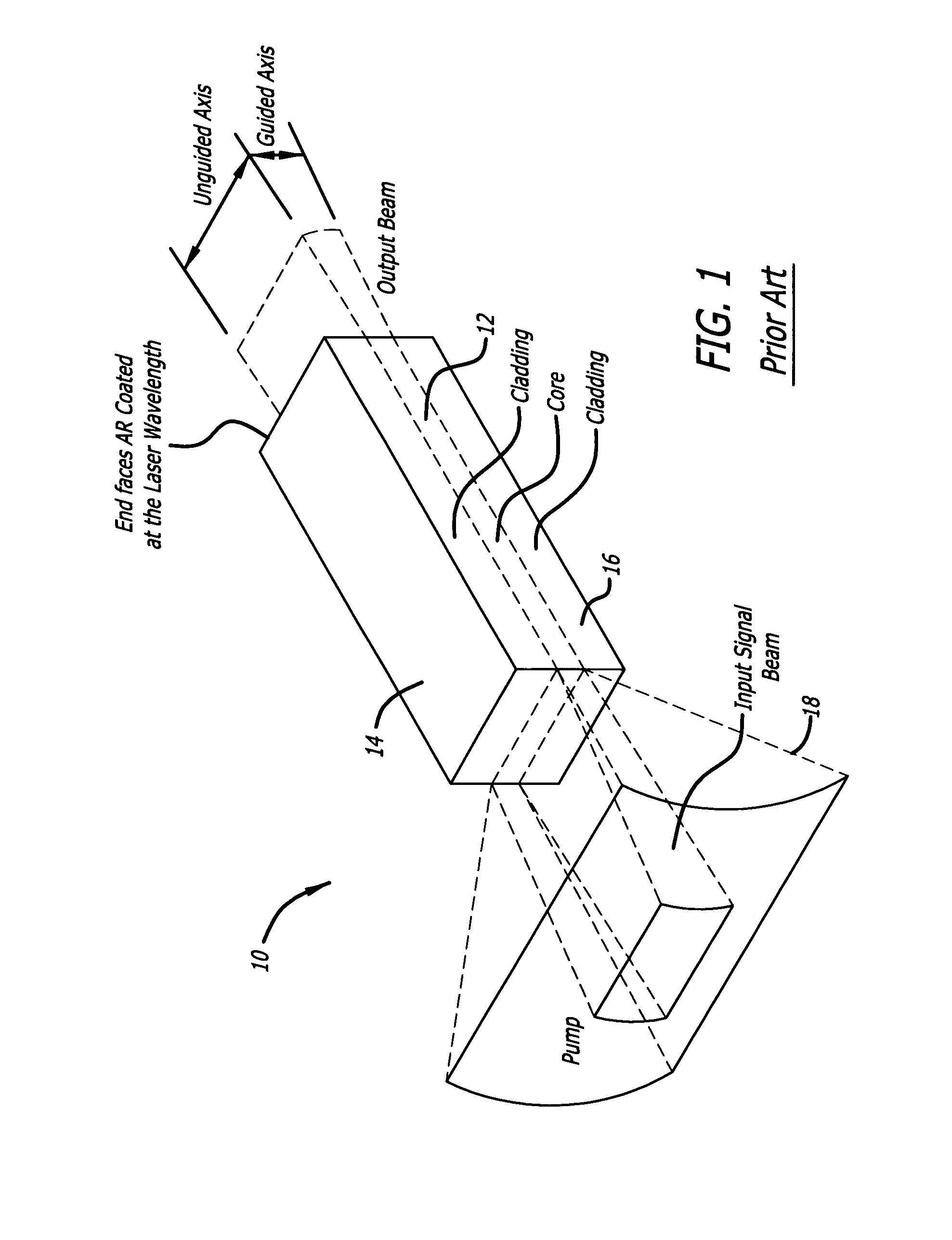
[0016]FIG. 1 is a simplified perspective view of a planar waveguide implemented in accordance with an illustrative embodiment of the present teachings.

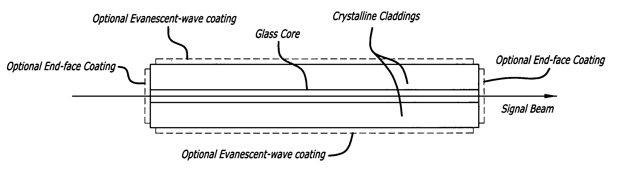
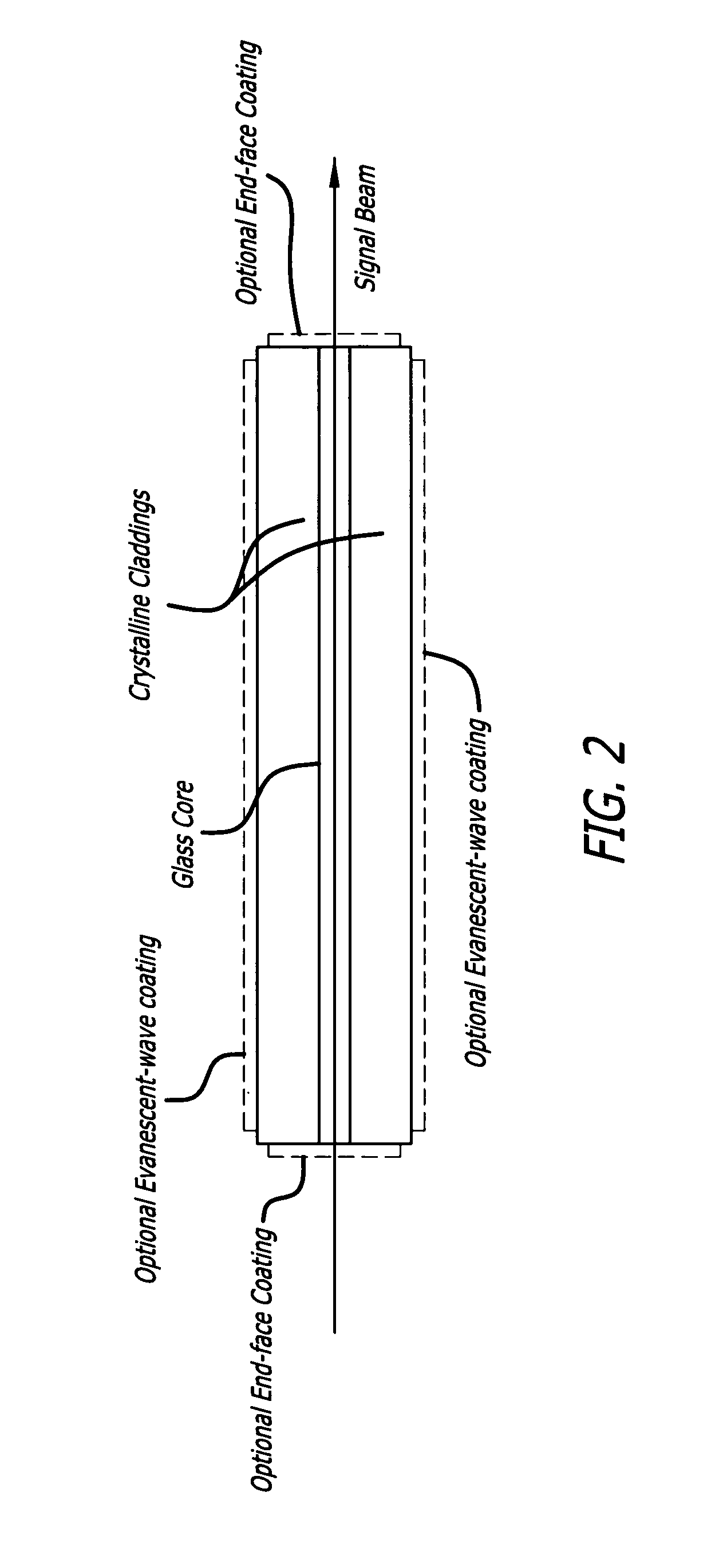
[0017]FIG. 2 is a sectional side view of the planar waveguide of the present invention.

[0018]FIG. 3 is a sectional end view of the planar waveguide of the present invention.

[0019]As shown in FIG. 1, th...


PUM

PropertyMeasurementUnit
thicknessaaaaaaaaaa
thickness aspect ratioaaaaaaaaaa
refractive indexaaaaaaaaaa

Abstract

A planar waveguide with a glass core and a crystalline cladding. In a specific embodiment, the core is doped preferably with Neodymium, Ytterbium, or Erbium. In the best mode, the core is athermal glass with a refractive index uniformity 10−6 or better and the crystalline cladding has a refractive index lower than that of the core by 10−4 to 10−3 with a refractive index uniformity of 10−4. The cladding has high transparency at pump and lasing wavelengths. The coefficient of thermal expansion of the cladding is close to that of the core. In illustrative embodiments, the cladding is Sapphire and the core is aluminate glass. In an alternative embodiment, the cladding is crystal quartz and the core—is phosphate glass. By utilizing different materials for the core and cladding, the properties of each are optimized. Use of glass for the core allows much more flexibility in tailoring the properties of the core and the PWG geometry readily accommodates the low thermal conductivity of a glass core because the overall thermal performance is dominated by the higher thermal conductivity of the crystalline cladding.

Description

BACKGROUND OF THE INVENTION[0001]1. Field of the Invention[0002]The present invention relates to optical devices. More specifically, the present invention relates to laser amplifiers.[0003]2. Description of the Related Art[0004]High-energy lasers are used in a variety of applications. For example, laser weapon applications currently require output power levels ranging from tens of kilowatts to a few megawatts. To date, only chemical lasers have been scaled to the megawatt level. Unfortunately, chemical lasers are very large and produce toxic byproducts making them unsuitable for many applications.[0005]Compact, efficient, diode-pumped solid-state lasers have been considered for such high power applications. However, these lasers are typically limited to a few kilowatts per laser crystal due to both the limited size of available crystal materials and the challenges in removing the waste heat form the gain medium. These limitations have led to approaches to solid-state high-energy las...

Claims


Application Information

Patent Timeline
Patent Type & Authority Patents(United States)
IPC IPC(8): G02B6/10G02B6/12H01S3/06H01S3/063H01S3/0941H01S3/16H01S3/17
CPCH01S3/0632G02B6/12H01S3/0612H01S3/0623H01S3/0625H01S3/09415H01S3/1608H01S3/1618H01S3/1643H01S3/17
Inventor FILGAS, DAVIS M.
Owner RAYTHEON CO
Why Eureka
Try Eureka