Laser ultrasonic flaw detection apparatus

a flaw detection and ultrasonic technology, applied in the direction of instruments, specific gravity measurement, magnetic property measurement, etc., can solve the problems of thermoelastic effect and ultrasonic vibration generation, and achieve the effect of reducing the size of the apparatus, facilitating handling, and simplifying the configuration of the apparatus

Active Publication Date: 2015-03-17
MITSUBISHI HEAVY IND LTD
View PDF20 Cites 17 Cited by
  • Summary
  • Abstract
  • Description
  • Claims
  • Application Information

AI Technical Summary

Benefits of technology

[0026]With a laser ultrasonic flaw detection apparatus of the present invention, because the apparatus configuration is simplified and the apparatus size is reduced, when changing / adjusting an irradiation position of a laser beam on an inspection object, the apparatus can be easily handled. Moreover, with the laser ultrasonic flaw detection apparatus of the present invention, because the control ranges for the output power and pulse width of the laser beam are large, the output power and pulse width of the laser beam can be set to optimal levels in accordance with the type and size of the inspection object.

Problems solved by technology

First, when a first laser beam is focused onto a surface of an inspection object, ultrasonic vibrations are generated due to the thermoelastic effect.

Method used


Image

  • Laser ultrasonic flaw detection apparatus
  • Laser ultrasonic flaw detection apparatus
  • Laser ultrasonic flaw detection apparatus

Examples


Embodiment Construction

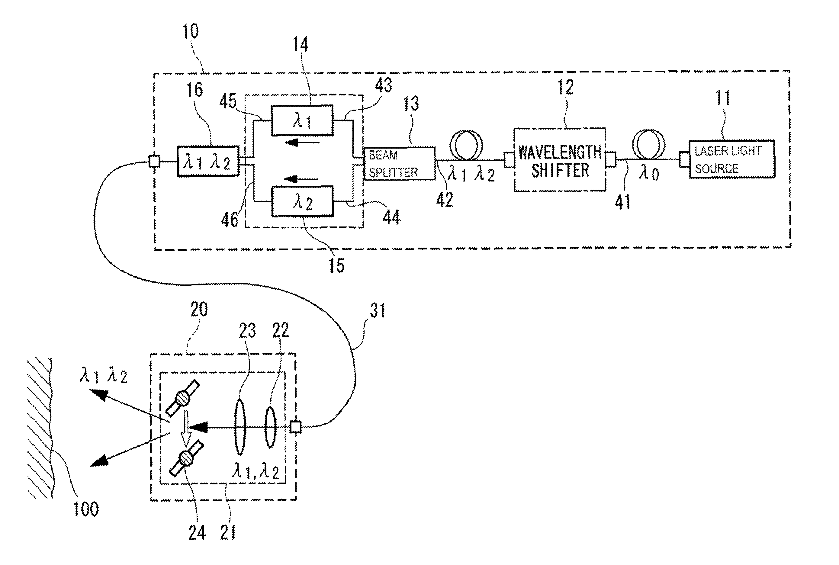
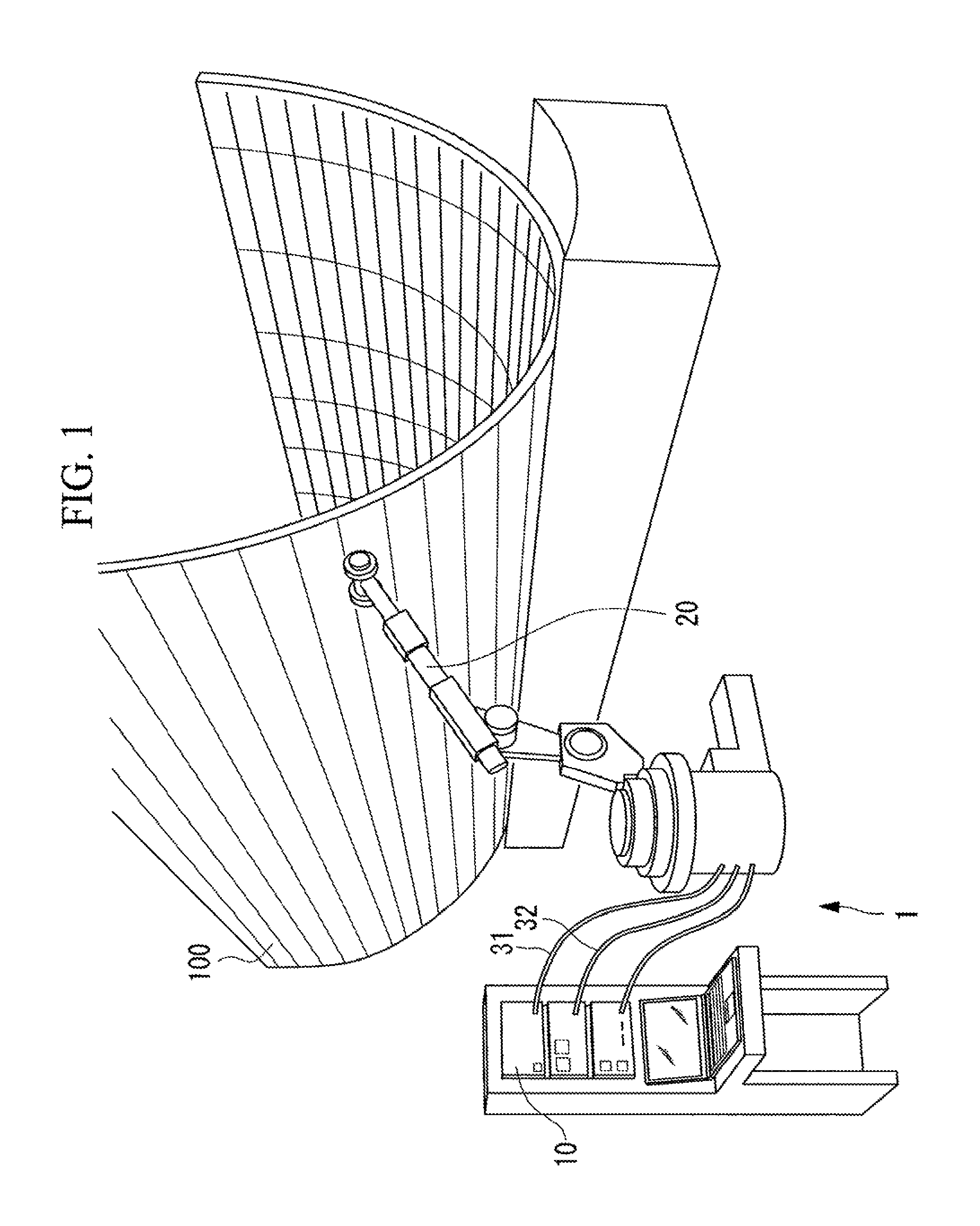
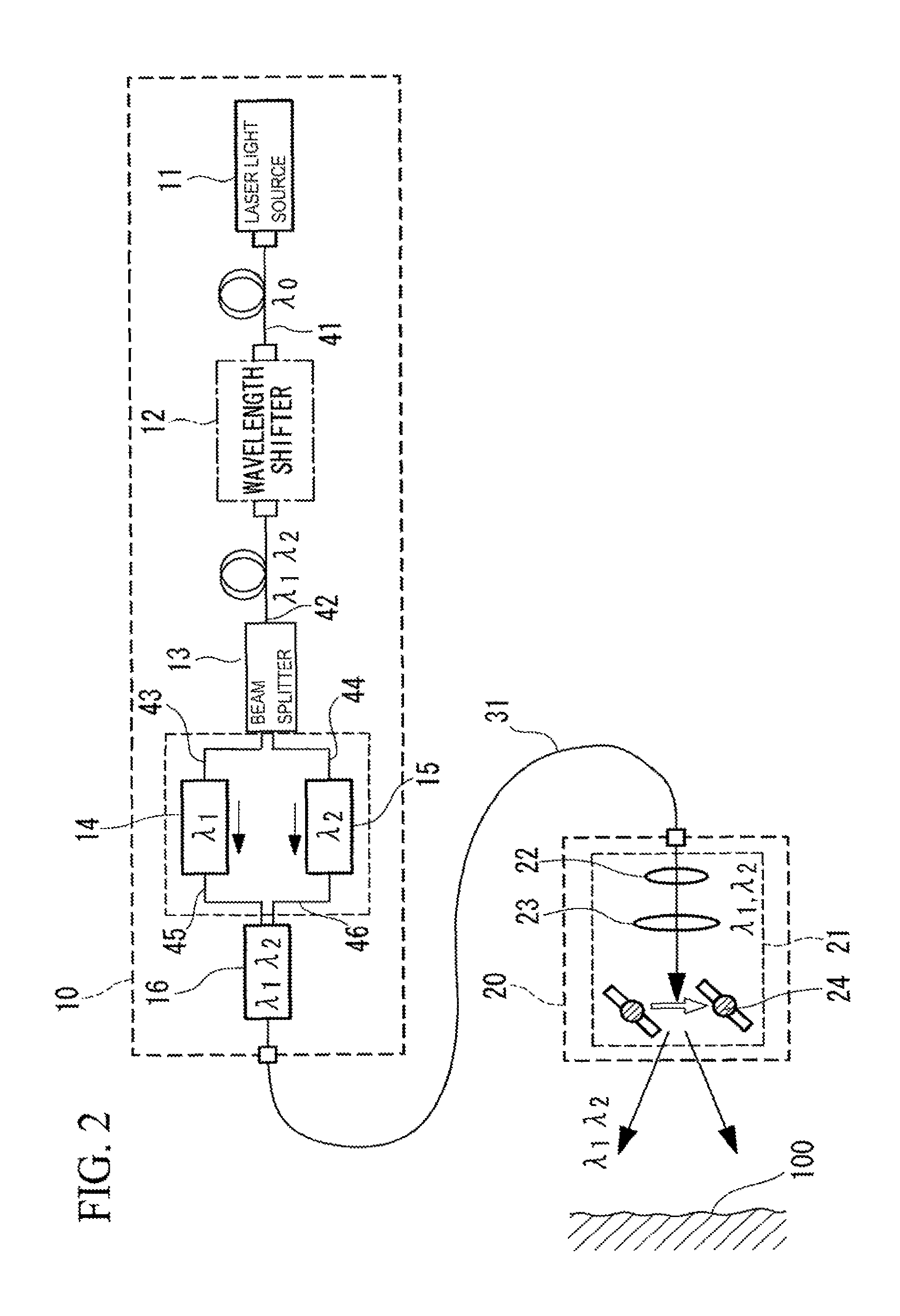
[0033]An embodiment of a laser ultrasonic flaw detection apparatus according to the present invention will be described below with reference to the drawings.

[0034]A laser ultrasonic flaw detection apparatus according to this embodiment focuses a first laser beam onto a surface of an inspection object. In addition, the laser ultrasonic flaw detection apparatus focuses a second laser beam, which is different from the first laser beam, onto the surface of the inspection object. Accordingly, a vibration displacement at the surface of the inspection object excited by ultrasonic waves generated by the first laser beam is superimposed on reflected waves of the second laser beam reflected at the surface of the inspection object. By detecting the reflected waves of the second laser beam, the laser ultrasonic flaw detection apparatus acquires the vibration displacement excited at the surface of the inspection object due to the ultrasonic waves generated by the first laser beam, and detects th...


PUM

PropertyMeasurementUnit
laser ultrasonic flaw detectionaaaaaaaaaa
wavelengthsaaaaaaaaaa
wavelengthaaaaaaaaaa

Abstract

A laser beam having a single wavelength emitted from a laser light source is converted at a wavelength shifter into a laser beam having at least two wavelengths, which is further demultiplexed at a beam splitter into a laser beam having a first wavelength and a laser beam having a second wavelength. The output power and pulse width of the laser beam having the first wavelength are adjusted by a first controller so as to reach levels appropriate for generating ultrasonic vibrations without causing damage to an inspection object. The output power and pulse width of the laser beam having the second wavelength are adjusted by a second controller so as to reach appropriate levels for detecting the above-described ultrasonic vibrations. These laser beams are multiplexed by a multiplexer into a single laser beam to be focused onto a surface of the inspection object.

Description

TECHNICAL FIELD[0001]The present invention relates to a laser ultrasonic flaw detection apparatus that is employed to perform non-destructive flaw detection of a defect or the like inside an inspection object.BACKGROUND ART[0002]In recent years, the use of composite materials is increasing in aerospace, automobile and other industries for the purpose of reducing product weight, etc. A laser ultrasonic flaw detection apparatus is employed as a method of non-destructively evaluating the structural integrity of such composite materials, etc.[0003]The principle of this laser ultrasonic flaw detection apparatus will be briefly described. First, when a first laser beam is focused onto a surface of an inspection object, ultrasonic vibrations are generated due to the thermoelastic effect. Specifically, the surface of the inspection object is heated by the laser beam; the volume of the inspection object expands along with this increase in temperature, thus generating stress; and ultrasonic v...

Claims


Application Information

Patent Timeline
Patent Type & Authority Patents(United States)
IPC IPC(8): G01N29/04G01N21/41G01N29/24
CPCG01N29/2418G01N2291/044G01N2291/0231G01N29/348G01N29/42
Inventor ISHIOKA, MASAHITO
Owner MITSUBISHI HEAVY IND LTD
Why Eureka
Try Eureka