
Adaptive threshold voltage for frequency input modules

a threshold voltage and frequency input technology, applied in the direction of resistance/reactance/impedence, instruments, measurement devices, etc., can solve the problems of loss of signal integrity, random noise and ringing of electrical signals, and electrical signals produced by sensors are often subject to noise and distortion, so as to maximize the amount of emi rejection and less time to commission and adjust sensors

Active Publication Date: 2015-03-17
ROCKWELL AUTOMATION TECH
View PDF16 Cites 3 Cited by
  • Summary
  • Abstract
  • Description
  • Claims
  • Application Information

AI Technical Summary

Benefits of technology

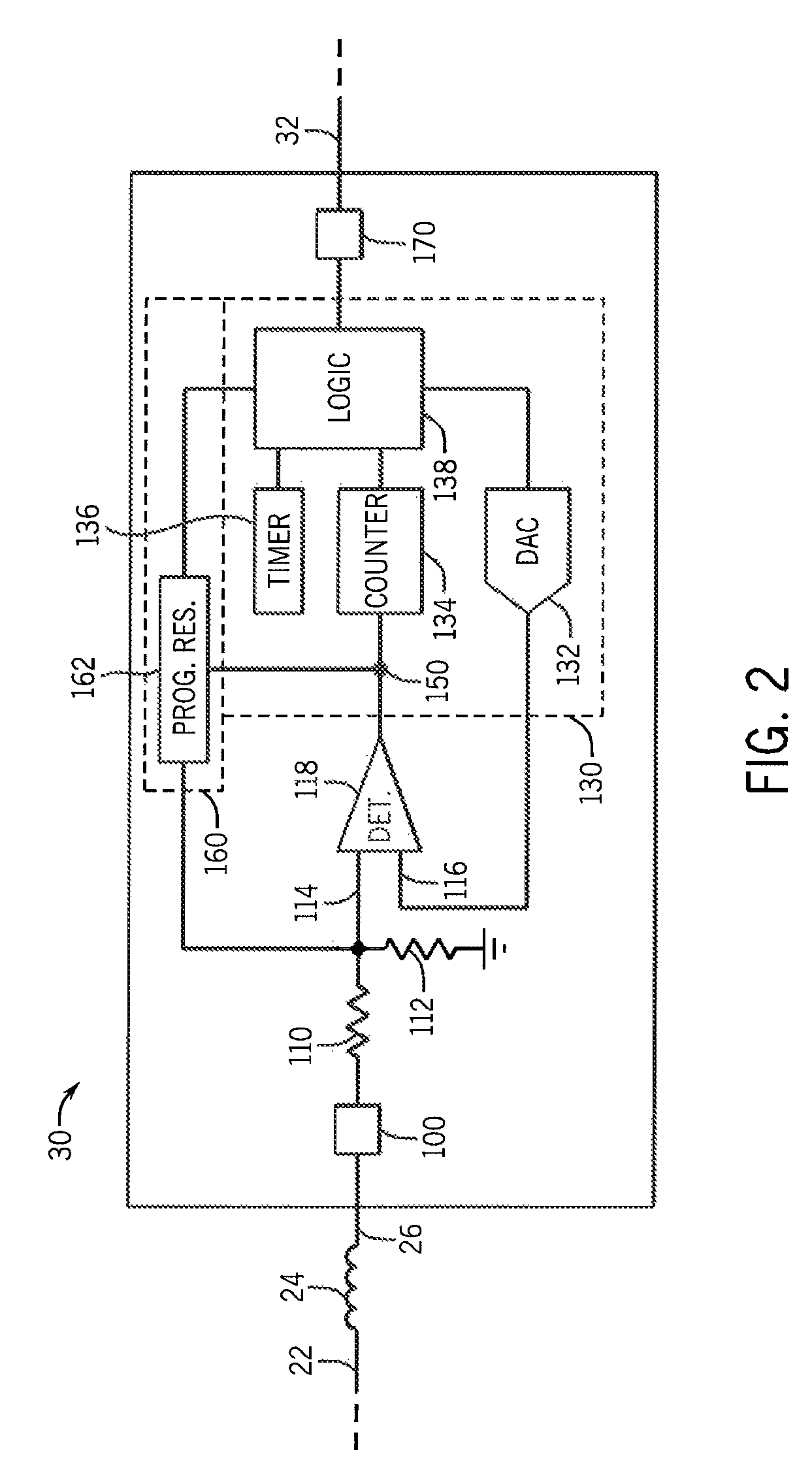
The present invention provides a way to automatically adjust the detection threshold of variable reluctance type sensors based on the frequency of the received signal. This allows for better trade-offs between threshold level, noise resistance, and sensitivity to sensor signal. Additionally, the invention improves the ability of the I / O controller circuit to distinguish between actual input pulses and unwanted EMI induced input pulses, resulting in less time to commission and adjust a sensor, fewer false frequency measurements and less system down time.

Problems solved by technology

In application, the electrical signals produced by sensors are often subject to noise and distortion due to electromagnetic interference (EMI).
The result of EMI is a loss of signal integrity in the electrical signal, which may cause random noise and ringing to the electrical signal.
Such filtering inherently reduces the time resolution of the derived digital signal by removing high-frequency components of the sensed signal.
For this reason, the threshold used to produce the desired square wave signal can be a complicated exercise.
Placing the threshold too low will make the sensor susceptible to electrical noise whereas placing the threshold too high may cause the system to fail to detect low level signals from the variable reluctance sensor at low machine speeds.
Similar problems arise with respect to determining the amount of hysteresis that is optimum.

Method used


Image

  • Adaptive threshold voltage for frequency input modules
  • Adaptive threshold voltage for frequency input modules
  • Adaptive threshold voltage for frequency input modules

Examples


Embodiment Construction

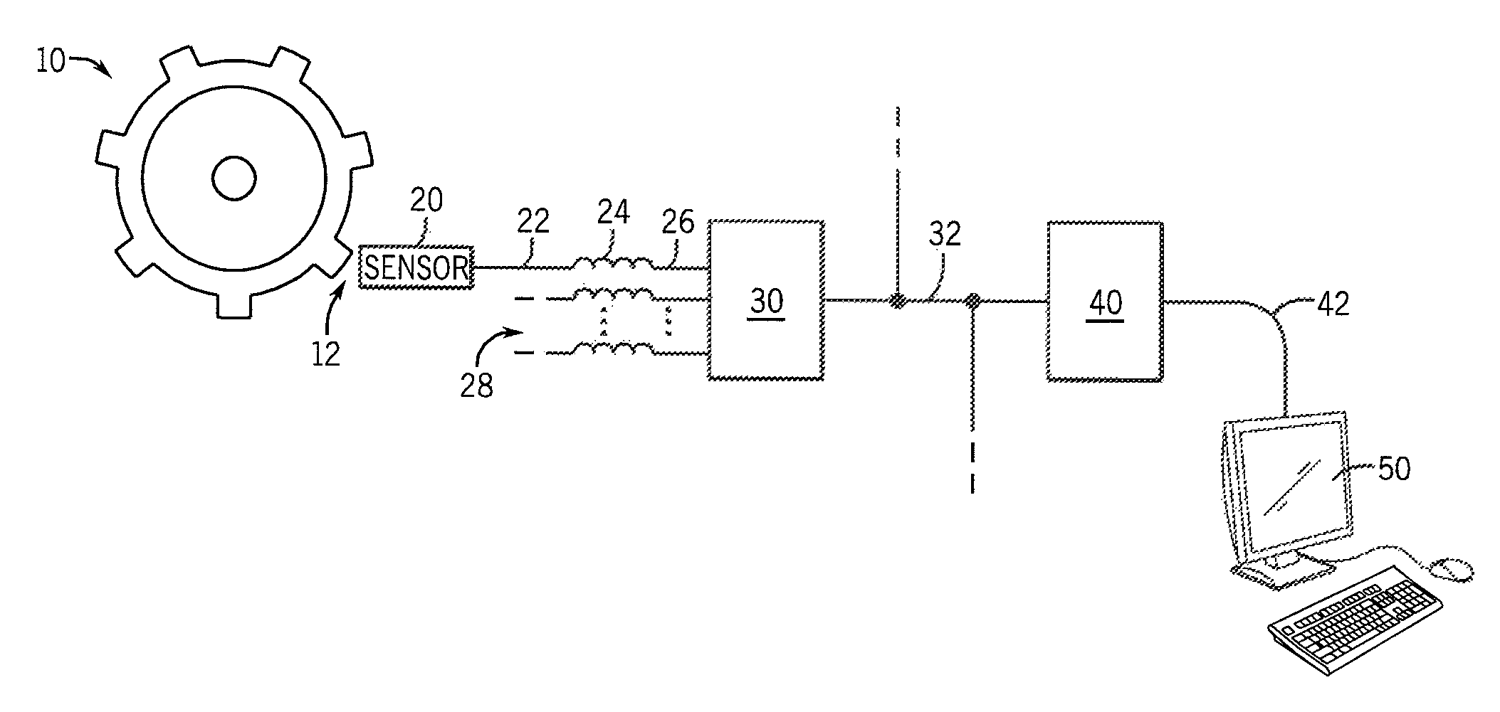
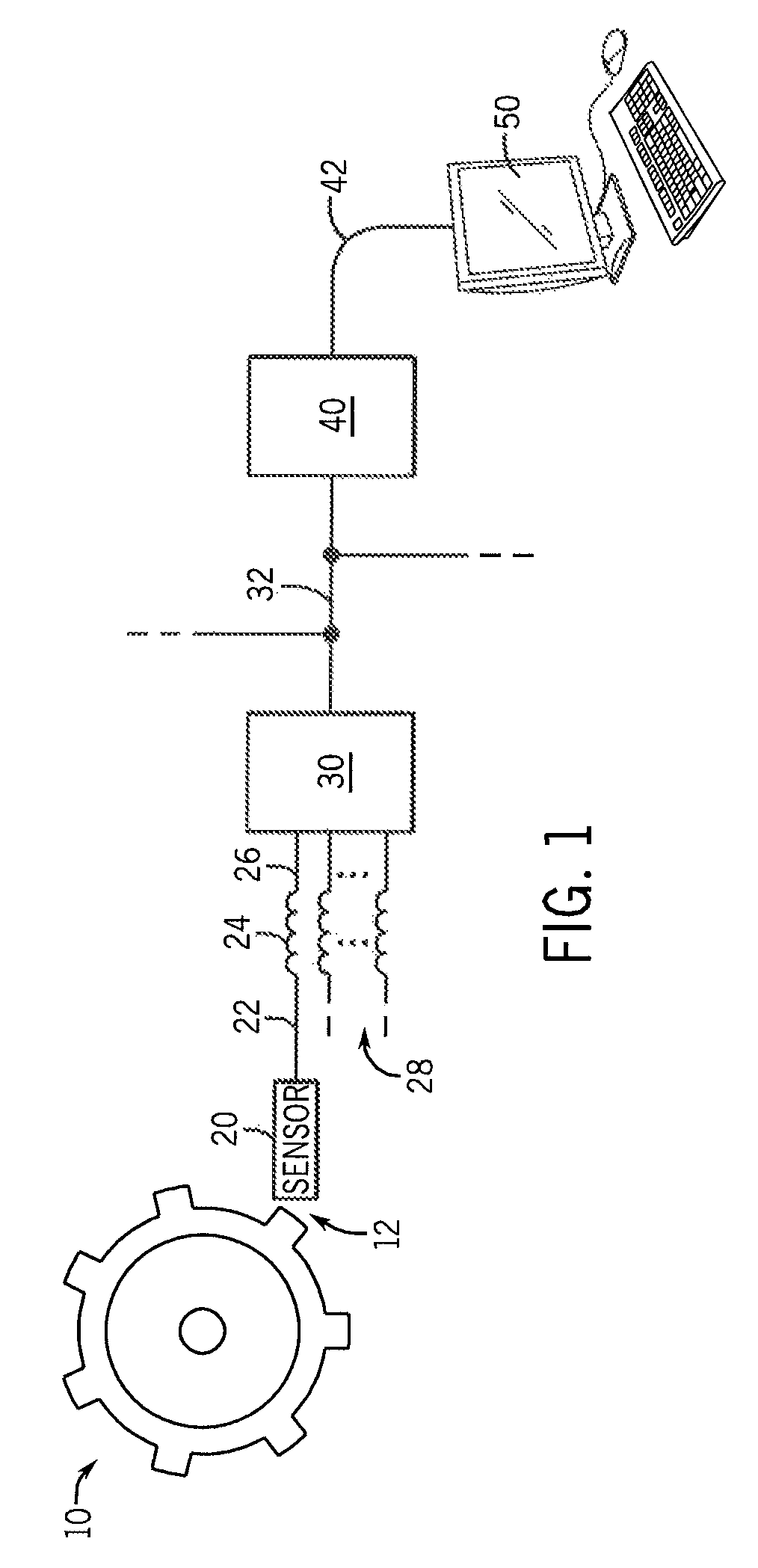
[0032]Referring now to FIG. 1, a large rotating toothed wheel 10 is shown as a moving machine in an industrial application system. The wheel 10 may be used in any various industrial applications, such as a turbine engine, a gear on an assembly line or a cooling fan. The wheel 10 may rotate with varying speeds ranging from stationary to as fast as the industrial system will allow, and could come alternatively in other shapes and with other periodic motions, such as a toothed rod moving linearly back and forth.

[0033]In close proximity to the wheel 10 is a sensor 20 which may detect variations in the electromagnetic field produced by the physical motion of the wheel 10 across a gap 12. The sensor 20 may be for example a variable reluctance sensor comprising a permanent magnet and a pick up coil as known in the art. In response to variations in the electromagnetic field, the sensor 20 produces an electrical input signal of varying frequency and amplitude that approximately corresponds t...


PUM


Abstract

Systems and methods for an industrial I / O controller circuit for frequency input modules that measure the frequency of an electrical input signal using adaptive threshold voltage and / or adaptive hysteresis feedback are shown and described. The systems and methods provide advantages in that the I / O controller circuit can better distinguish between actual input pulses from the electrical input signal, as opposed to unwanted Electromagnetic Interference (EMI) induced input pulses. This maximizes the amount of EMI rejection, independent of the frequency of the moving machine, and results in less time to commission and adjust a sensor, fewer false frequency measurements and less system down time.

Description

BACKGROUND OF THE INVENTION[0001]The present invention relates to industrial I / O controller circuits for industrial control systems, and in particular to industrial I / O controller circuits for frequency input modules that measure system frequencies using adaptive threshold voltage and / or adaptive hysteresis feedback.[0002]Industrial controllers are specialized computer systems used for the control of industrial processes or machinery, for example, in a factory environment. Industrial controllers typically comprise I / O controller circuits to accomplish different functions as part of the industrial control system. One such function is measuring the frequency or revolutions per minute (RPM) of a moving machine, such as a large rotating toothed wheel, so that some action may be taken by the industrial control system. For example, an industrial controller may comprise an I / O controller circuit used for measuring the frequency of a turbine engine so that additional power can be applied to...

Claims


Application Information

Patent Timeline
Patent Type & Authority Patents(United States)
IPC IPC(8): G01R23/16G01D5/244
CPCG01D5/2448
Inventor VAZACH, JOSEPH G.
Owner ROCKWELL AUTOMATION TECH
Learn More