Optical characteristic measuring apparatus

a measuring apparatus and optical characteristic technology, applied in the direction of optical radiation measurement, instruments, spectrophotometry/monochromators, etc., can solve the problems of inapplicability, measurement reflectance of the sample becomes larger than an actual value, and the measurement precision of measured quantities is different from each other. to achieve the effect of wide wavelength region

Active Publication Date: 2015-03-17
NAT INST OF ADVANCED IND SCI & TECH
View PDF18 Cites 2 Cited by
  • Summary
  • Abstract
  • Description
  • Claims
  • Application Information

AI Technical Summary

Benefits of technology

[0017]A conventional scatterometer (see Japanese Patent Application Laid-Open Publication No. 2010-276363) which rotates a light-receiving ellipsoidal mirror to perform measurement, and which was developed by the present inventor, can perform three measurements: hemisphere total reflectance, hemispherical total transmittance, and light distribution measurement. However, it was found that there are two problems to be solved. This scatterometer can shorten the time to measure light distribution as compared with a gonioreflectometer, but the measurement time is longer than in the case of an imaging hemisphere or the like. In order to measure hemisphere total reflectance (transmittance), it is necessary to integrate a quantity measured at each angle of rotation, but quantitative analysis is difficult.
[0032]In the present invention, a combination of a rotational parabolic mirror and a reflective surface mirror (a parabolic mirror or an ellipsoidal mirror) makes it possible to match light diffusing over a solid angle of the hemisphere with a light-receiving solid angle of the CCD camera. In the hemispherical detection optical system using a hemispherical lens or the like, since the refraction index of the lens or the like depends on wavelength, it is necessary to change the material of the hemispherical lens or the fiber taper in the middle, in order to measure a wide wavelength region. On the other hand, when a rotational parabolic mirror and a reflective surface mirror are used in combination, it is reflective optical system and there is no wavelength dependence, so that a wide wavelength region of ultraviolet, visible, and infrared regions can be covered by a single hemispherical detection optical system.

Problems solved by technology

A drawback of this method lies in the fact that their measurement precisions of measured quantities differs from each other.
This scatterometer was researched and developed until the 1980's, but was not put into practical use.
This occurs repeatedly, and thereby causes the problem that measured reflectance of the sample become larger than an actual value.
However, this scatterometer has the problem that light distribution cannot be measured (see FIG. 16 in Japanese Patent Application Laid-Open Publication No. 2010-276363).
However, a detector has to be scanned in 47 space, and therefore there is the problem that a set of measurements takes a long time.
However, since this measuring method includes many assumptions, it impossible to perform an exact quantitative measurement.
In this structure, absolute reflectance measurement is impossible, only relative reflectance can be measured, and transmittance measurement is also impossible.
Also regarding diffuse reflection measurement, only scattered light incident on one ellipsoidal surface can be measured, but there is the problem that quantitative measurement is impossible.
However, it was found that there are two problems to be solved.
In order to measure hemisphere total reflectance (transmittance), it is necessary to integrate a quantity measured at each angle of rotation, but quantitative analysis is difficult.
However, a beam exiting from the hemispherical lens with the solid angle of one seventh of this hemisphere is about 10 mm in diameter, which is larger than the size of the imaging surface of the CCD camera (for example, 7 mm in length and 5.3 mm in width), and therefore all light cannot be taken into the CCD camera.

Method used


Image

  • Optical characteristic measuring apparatus
  • Optical characteristic measuring apparatus
  • Optical characteristic measuring apparatus

Examples


first embodiment

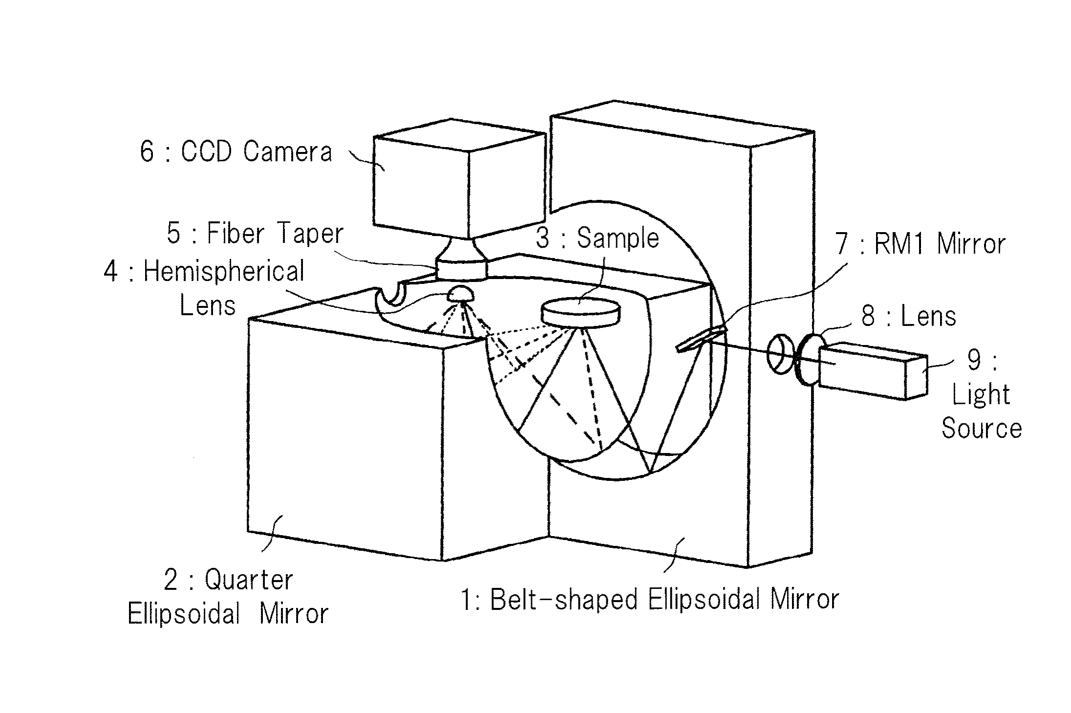
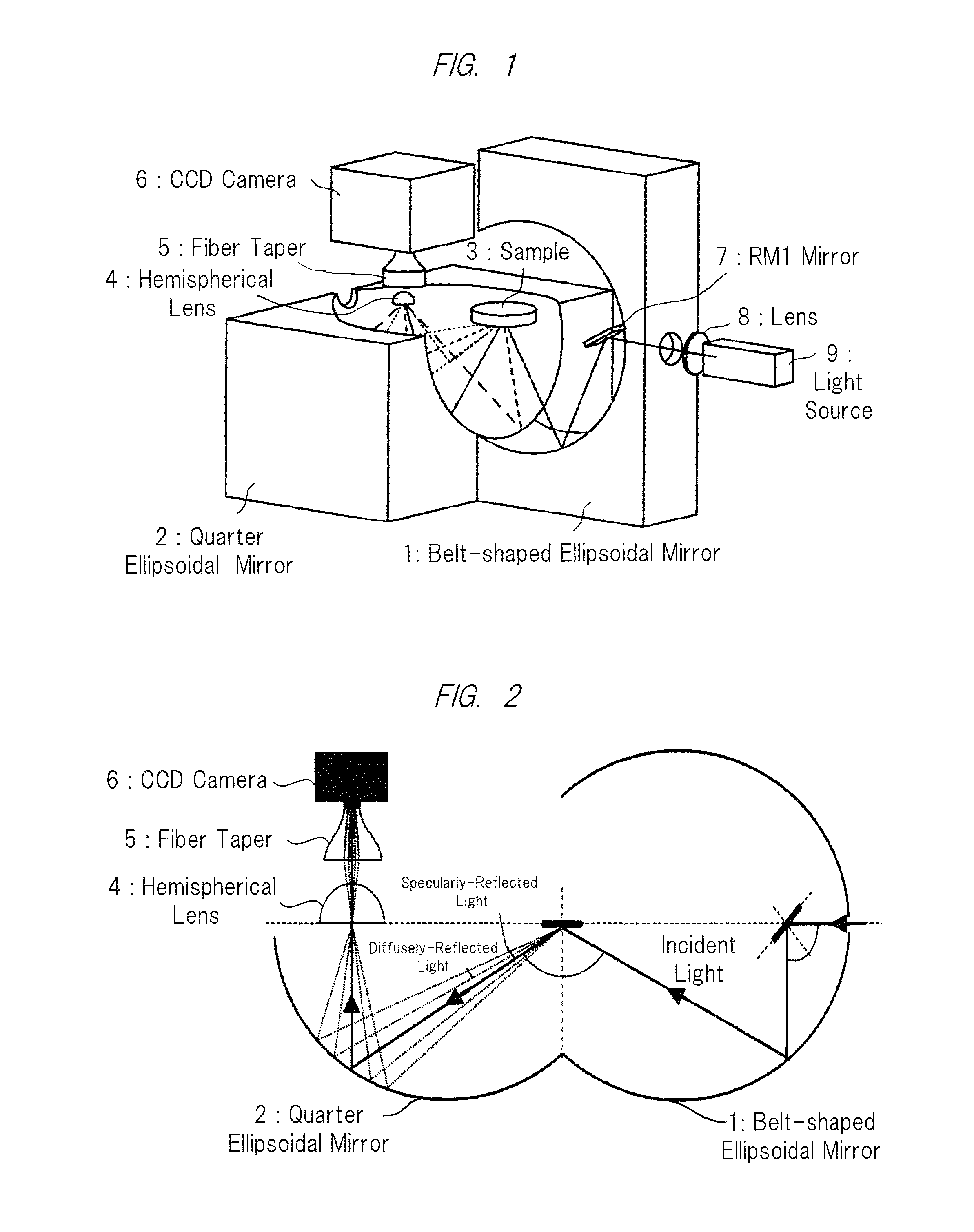
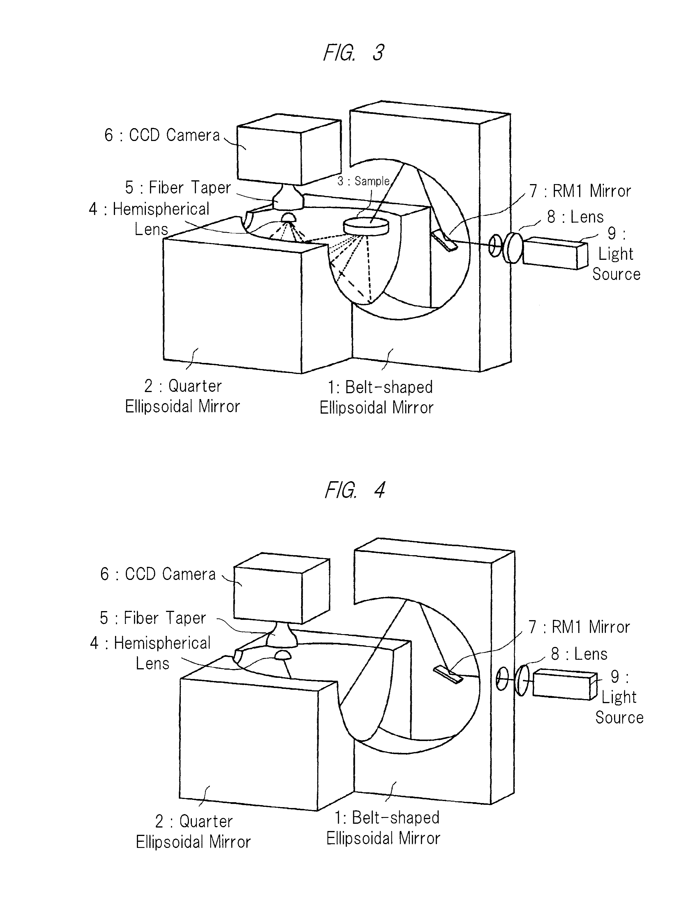
[0060]A representative structure, an evaluation result and the like of an optical characteristic measuring apparatus for measuring scattered light from a sample will be described below. FIG. 1 is a perspective view showing a representative structure of a first embodiment and showing a reflection measuring arrangement. FIG. 2 is a cross-sectional view schematically showing the apparatus of FIG. 1 and showing a reflection measuring mode. FIG. 3 is a view showing a transmission measuring arrangement. FIG. 4 is a view showing a background measuring arrangement. FIG. 5 is a view showing a hemispherical detection optical system. FIG. 6 is a view showing a belt-shape ellipsoidal mirror. FIG. 7 is a view showing a quarter ellipsoidal mirror. FIG. 8 is a view showing an octantal ellipsoidal mirror. FIGS. 9, 10, and 11 are views showing the rotation of the belt-shape ellipsoidal mirror.

[0061]Firstly, as a precondition for the present invention, a double ellipsoidal optical system will be desc...

second embodiment

[0093]In the first embodiment, the example using a hemispherical lens, a fiber taper, and a CCD camera, and the example using a hemispherical lens, a fiber taper, and a photo diode detector, as a hemispherical detection optical system, are described. In a second embodiment, the example using a convex lens system instead of the fiber taper will be described with reference to FIG. 22. In FIG. 22, a point at which five solid lines, and a dashed-dotted line, and a dashed-two dotted line gather is a focal point F2 of the ellipsoidal mirror. The center of the hemispherical lens is disposed so as to coincide with the focal point F2 of the ellipsoidal mirror. In addition, the bottom surface of the hemispherical lens is disposed parallel to an edge face of the quarter ellipsoidal mirror. This prevents the hemispherical detection optical system from making a shadow inside the ellipsoidal mirror, and therefore the hemispherical lens can concentrate all light collected from the 2π space on the ...

third embodiment

[0097]In the second embodiment, one example of using a hemispherical lens, convex lenses, and a CCD camera (or a photo diode detector) is described as a hemispherical detection optical system. In the third embodiment, one example of using a rotational parabolic mirror 14 instead of the hemispherical lens 4 will be described with reference to FIG. 23. A hemispherical detection optical system according to the third embodiment comprises a rotational parabolic mirror 14, a convex lens system (convex lens) 13, and a CCD camera 6. The rotational parabolic mirror 14 has a shape cut (opening) along a plane perpendicular to the axis of rotation and passing through the focal point, and has a polished inner surface, and this mirror is disposed so that the cut plane (opening) passing through the focal point of this mirror is parallel to the edge of the quarter ellipsoidal mirror, and the focal point of this mirror coincides with that of the quarter ellipsoidal mirror.

[0098]A dashed-dotted line ...


PUM

PropertyMeasurementUnit
reflectanceaaaaaaaaaa
timeaaaaaaaaaa
lengthaaaaaaaaaa

Abstract

In an apparatus for measuring an optical characteristic of a sample, one object of the present invention is to provide an apparatus capable of measuring hemispherical total reflectance, hemispherical total transmittance, and light distribution, and to achieve a reduction in measurement time and an improvement in precision of the quantitative analysis of hemispherical total reflectance (transmittance). In a double ellipsoidal optical system which is an optical system in which one focal points of two ellipsoidal mirrors are positioned as a common focal point, and three focal points are aligned in a straight line, the double ellipsoidal optical system is composed of a partial ellipsoidal mirror 2, such as a quarter ellipsoidal mirror, and a belt-shape ellipsoidal mirror 1. By disposing, on a position of a focal point of the partial ellipsoidal mirror, a hemispherical detection optical system having a hemispherical lens or a rotational parabolic mirror, light scattered by an object, reflected by the partial ellipsoidal mirror, and focused on the point is photographed by for example a CCD camera 6 via a hemispherical lens and a taper fiber 5 so as to measure an optical characteristic of the object.

Description

CROSS REFERENCE TO RELATED APPLICATIONS[0001]The present application claims priority from International Patent Application Serial No. PCT / JP2012 / 055945 filed Mar. 8, 2012 and Japanese Patent Application No. 2011-050104 filed on Mar. 8, 2011, the contents of which are hereby incorporated by reference into this application.TECHNICAL FIELD[0002]The present invention relates to a highly-sensitive optical characteristic measuring apparatus capable of causing light to fall on an object such as a sample, and measuring light intensity and spatial distribution of scattered light from the sample. In particular, the present invention relates to a scatterometer capable of measuring efficiently total spherical scatter of an object.BACKGROUND ART[0003]In recent years, improvements in measurement precision of an optical characteristic inspection apparatus has been needed in precise measurement in the manufacture of electronic parts such as a semiconductor product, or in the field of nanotechnologi...

Claims


Application Information

Patent Timeline
Patent Type & Authority Patents(United States)
IPC IPC(8): G01N21/49G01N21/47G01N21/59G02B19/00
CPCG01N21/4738G01N21/474G01N21/59G02B19/0085G02B19/0023G01N2201/0637G01N2021/4714
Inventor KAWATE, ETSUOHAIN, MIROSLAV
Owner NAT INST OF ADVANCED IND SCI & TECH
Why Eureka
Try Eureka