Method and device for cooling of IR emitters for preforms

a technology of ir emitters and cooling devices, which is applied in the direction of dryers, stoves or ranges, furnaces, etc., can solve the problems of higher wear out and faster damage of emitters

Active Publication Date: 2015-03-17
KRONES AG
View PDF28 Cites 4 Cited by
  • Summary
  • Abstract
  • Description
  • Claims
  • Application Information

AI Technical Summary

Benefits of technology

[0012]The energy efficiency can be increased by using the IR lamps under very high temperatures and / or by reducing the distance between the IR emitters and the back reflector. But these measurements lead to a faster damage and a higher wear out of the emitters.
[0013]To solve the problem a cooling of the lamps or emitters was developed according to the present invention. Hereby a coolant air flow passes behind and / or around the bulbs and sockets of the lamps or emitters. By this the temperature of the emitters can be reduced to an acceptable level thereby ensuring a higher durability.
[0018]The first and the second coolant flow unite above the arrangement of the IR emitters. According to one preferred embodiment of the invention the first coolant flow has a higher velocity than the second coolant flow. This leads to a suction effect that further supports and encourages the upwardly directed drainage of the second coolant flow. Thereby the temperature of the emitter can be dramatically reduced. It could be shown that by these measures the temperature of the emitters can be reduced by about 200° C.
[0021]The described means for cooling of emitters improve the energy efficiency. This can also be derived from the Stefan Boltzman law. Generally speaking, the hotter the coil, the better the emitter. When the temperature of the emitter bulb is actively cooled, a hotter coil can be used. According to the Stefan Boltzman lawP=σ·A·T4 (whereby P=radiant power; σ=Boltzmann constant; A=area of the body and T=absolute temperature)the radiant power of a body changes in proportion to the fourth potency of its absolute temperature, therefore a massive increase in radiant power can be achieved by increasing the temperature of the coil.

Problems solved by technology

But these measurements lead to a faster damage and a higher wear out of the emitters.

Method used


Image

  • Method and device for cooling of IR emitters for preforms
  • Method and device for cooling of IR emitters for preforms
  • Method and device for cooling of IR emitters for preforms

Examples


first embodiment

[0047]FIG. 3 shows means for the cooling of emitters. Hereby especially and / or additionally the thread coolant flow 50 shall be used to cool the emitters 35. The thread coolant flow 50 is arranged above the surface coolant flow 52. The thread coolant flow 50 directly blows cold air onto the thread or mouth region 22 of the preforms 20. A part of the thread coolant flow 50 is branched off by a cooling plate 60 comprising at least one air conductor 62. The branched off air is used as an emitter coolant flow 51 and diverted downwards in a direction BR so that it passes behind the emitters 35. Thereby the emitters 35 are actively cooled. Furthermore the air behind the emitters 35 is transported optimally downwards. An air cushion of hot air is avoided which further optimizes the cooling of the emitters 35.

[0048]FIG. 4 and FIG. 5 show different representations of a coolant plate 60 with a plurality of coolant conductors 62. The coolant plate 60 is used to branch off the second coolant fl...

second embodiment

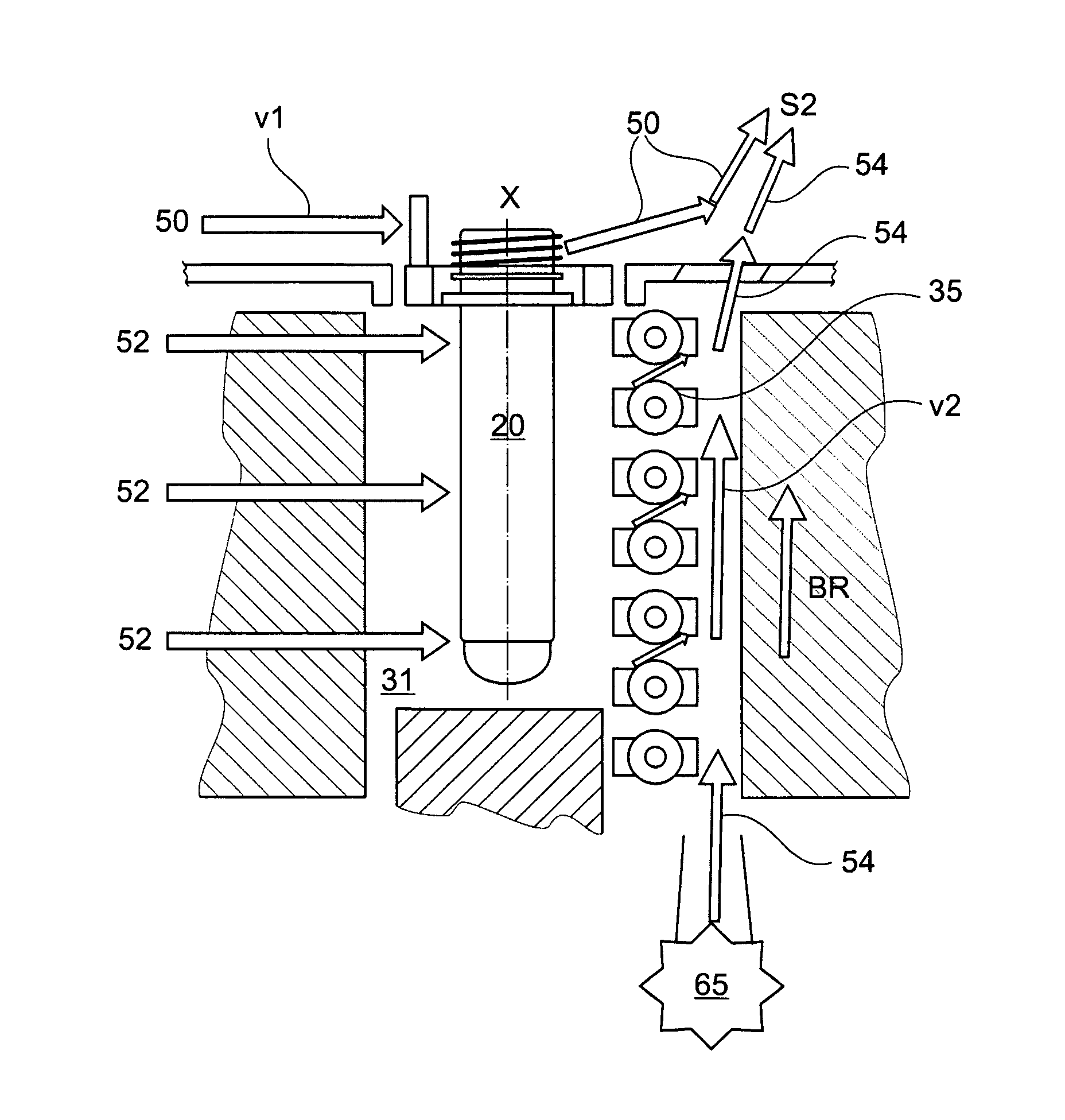
[0050]FIG. 7 shows means for the cooling of emitters. In this embodiment an emitter coolant flow 54 is generated by a coolant producing device 65 and gets blown between the emitter bulbs 35 and the back reflector 43. This emitter coolant flow 54 cools the emitters 35 from behind.

[0051]The emitter coolant flow 54 can be generated in different ways. A fan, a blower, an air compressor, an air knife system or other suitable means can be used as coolant producing device 65.

[0052]FIG. 8 shows the suction of the coolant flow in the second embodiment of means for the cooling of emitters according to FIG. 7.

[0053]The emitter coolant flow 54 moves in direction BR parallel to the longitudinal axis of the preforms 20 between the emitters 35 and the back reflector 43 towards the mouth 22 of the preform 20. In the heating unit 33 the emitter coolant flow 54 moves upwards and is united with the thread coolant flow 50. Preferably the velocity v1 of the thread coolant flow 50 is higher than the velo...


PUM

PropertyMeasurementUnit
temperaturesaaaaaaaaaa
temperatureaaaaaaaaaa
velocityaaaaaaaaaa

Abstract

A method for cooling IR emitters in a heating device for warming preforms before processing them in a stretch blow or blow molding device. IR emitters are arranged on at least one sidewall of the heating device parallel to the transport direction of the preforms, with at least one back reflector arranged on the side of the IR emitters facing away from the performs. The preforms to be warmed include a mouth region and a longitudinal axis and the mouth region is cooled with a first coolant flow. An almost vertical second coolant flow passes between the IR emitters and the at least one back reflector, this second coolant flow being at least partially fed by the almost horizontal first coolant flow and / or is united with the almost horizontal first coolant flow. A heating device and cooling device are also provided.

Description

[0001]This claims the benefit of German Patent Application DE 10 2010 015 018.5, filed Apr. 14, 2010 and hereby incorporated by reference herein.[0002]The present invention regards a method for cooling IR emitters, a heating device for preforms and means for cooling of emitters.BACKGROUND[0003]Preforms made out of a thermoelastic material, for instance PET, are used for the production of plastic bottles. The preforms are first warmed or heated and than blow moulded into the desired form in a stretch blow or blow moulding device. The preforms are especially transported on conveying means through a heating device before being processed in the blowing station.[0004]During the currently used process the preforms are held in the heating device by a shaft that is located on a rotary bearing on a link of a transport chain. In a heating device a plurality of chain links with pivoted shafts are connected to form an endless circumferential transport chain. On the outer side of the straight si...

Claims


Application Information

Patent Timeline
Patent Type & Authority Patents(United States)
IPC IPC(8): D02J13/00B29B13/02B29B13/04B29C35/08B29C49/06B29C49/64
CPCB29C49/64B29B13/024B29B13/04B29C49/06B29C2035/0822B29C2949/0715B29C49/645B29C49/6835B29C49/6845
Inventor SCHOENBERGER, WOLFGANGHOLZER, CHRISTIANFISCHER, SIMON
Owner KRONES AG
Why Eureka
Try Eureka