Eureka AIR delivers breakthrough ideas for toughest innovation challenges, trusted by R&D personnel around the world.

Multi-alloy vertical semi-continuous casting method

a technology of vertical semi-continuous casting and multi-alloys, which is applied in the field of manufacturing of semi-finished products, can solve the problems of adversely affecting productivity and cost, non-negligible risk of subsequent delamination, and inconvenient use of hot co-rolling process for all types of alloys, and achieve the effect of reducing the number of macrosegregations

Inactive Publication Date: 2015-03-24
CONSTELLIUM ISSOIRE
View PDF19 Cites 6 Cited by
  • Summary
  • Abstract
  • Description
  • Claims
  • Application Information

AI Technical Summary

Benefits of technology

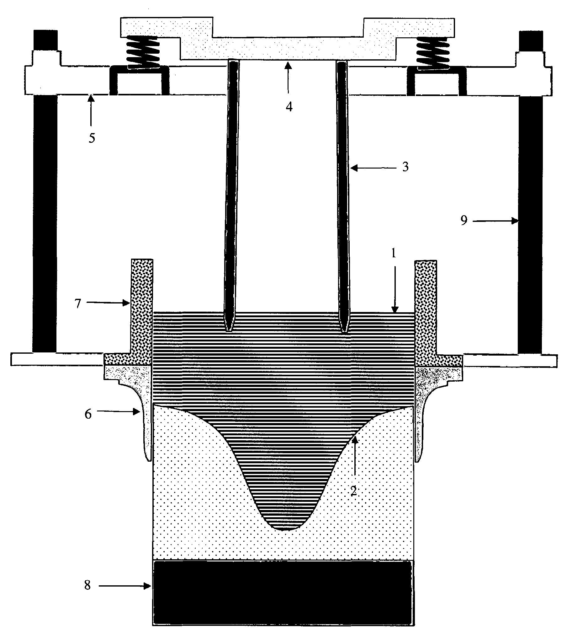
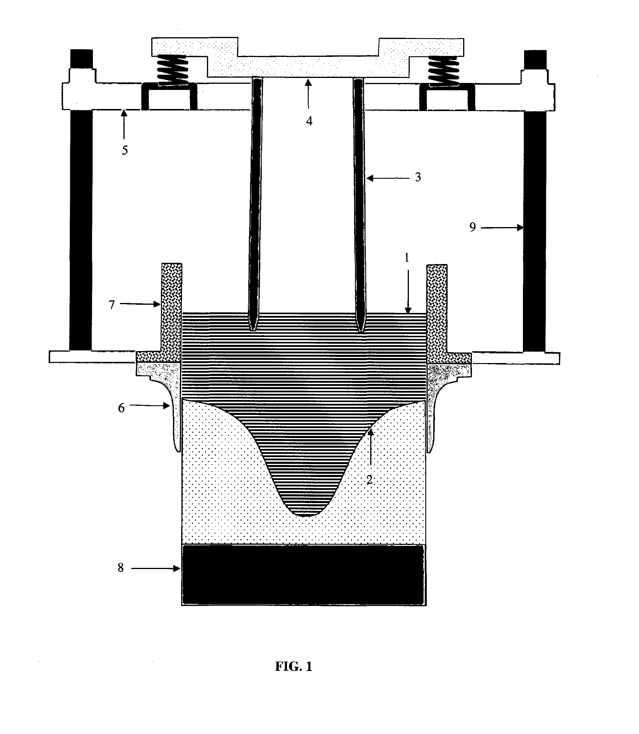
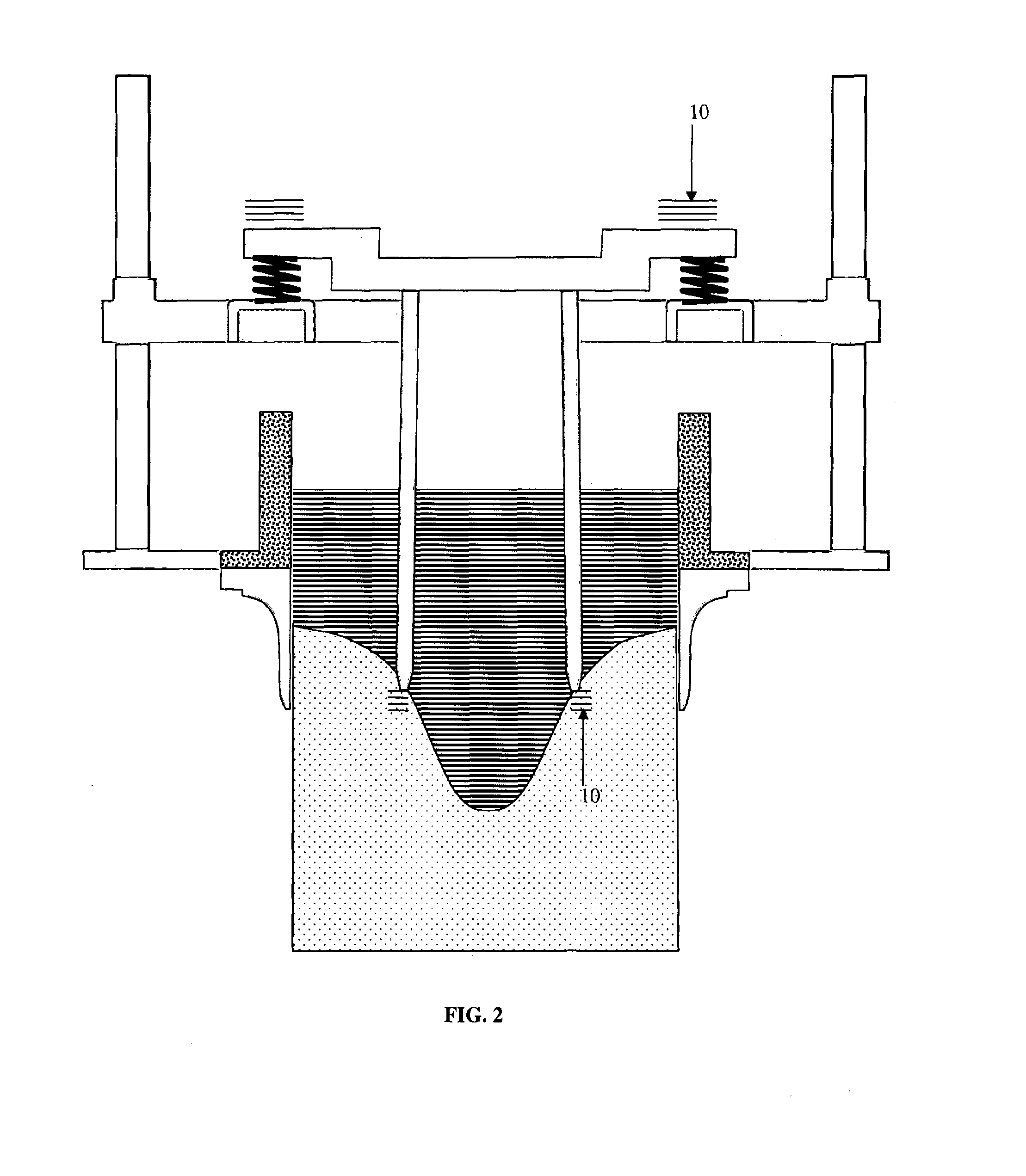
[0029]e) The solidified slab or billet is removed from the semi-continuous casting mould, characterized in that, by using a vibrator, a vibratory motion is applied to the separator, at least while it is in contact with the solidification front to prevent said separator from becoming trapped and entrained by the solidified metal.
[0039]In a particular mode, the aforementioned first and second alloys have be same composition. The applicant has observed that the vibratory motion exerts a beneficial effect by decreasing macrosegregation.

Problems solved by technology

In particular, such applications for aluminium, of which the above list is not exhaustive, require a compromise to be achieved between properties that are in many cases antagonistic, such as mechanical strength and workability, mechanical strength and corrosion resistance or suitability for drilling or turning.
However, this hot co-rolling process is not suitable for use with all types of alloy, particularly alloys containing significant quantities of zinc and / or magnesium (as used in the automotive, aeronautics and other industries) due to the susceptibility to surface oxidation of magnesium- and zinc-rich alloys.
In addition, double hot-rolling is very often necessary, adversely impacting productivity and costs.
A disadvantage of this solution is that it is technically challenging to implement, due in particular to the need to preheat a significant length of the metal foil, as well as issues relating to competition for space with the liquid metal supply systems, and above all, the fact that when two oxidized surfaces are introduced into the liquid metal a satisfactory metallurgical bond cannot be guaranteed, resulting in a non-negligible risk of subsequent delamination.
In addition, the inner surface of the outer layer is necessarily oxidized, again making it hard to ensure a satisfactory metallurgical bond between the two layers.
In other alloy combinations, obtaining a satisfactory metallurgical bond requires very tight control of the thermal transients.
In some cases, the desired result may be impossible to achieve.
As a result, significant convection currents form below the separator, causing relatively pronounced mixing of the two alloys, which are therefore not truly separated.
With this process too, a mixing area forms that is hard to reproducibly control in an industrial process; in addition, the process is limited by the fact that the two layers must be the same thickness by construction.

Method used


Image

  • Multi-alloy vertical semi-continuous casting method
  • Multi-alloy vertical semi-continuous casting method
  • Multi-alloy vertical semi-continuous casting method

Examples


example 1

[0068]This initial test is not consistent with the invention as the plate-type separator does not extend across the mould and only one cast of a single alloy was performed; the purpose of this test was to demonstrate the effectiveness of vibration as a means of preventing the plate from becoming entrained by the solidified metal.

[0069]A one-piece plate made of a glass-fibre and refractory composite material was introduced into and caused to vibrate in the casting pool for an AA1050 alloy rolling slab with cross-sectional dimensions of 1100×300 mm.

[0070]The refractory plate was 200 mm wide. It was inserted parallel to the large rolling surface, 65 mm from the mould wall.

[0071]The refractory composite plate was vibrated by means of a “Netter NTC” pneumatic vibrator, as used for emptying grain silos and hoppers. This vibrator unit generates low-amplitude, multi-directional vibrations.

[0072]The vibrating plate was brought into contact and held against the solidification front.

[0073]A ro...

example 2

[0076]The following materials were cast during this test:

[0077]a bi-alloy slab with an outer casing in AA5083 alloy and a core in AA7449 alloy, a typical composition for armour plating applications.

[0078]a bi-alloy slab with an outer casing in AA6016 alloy and a core in AA7021 alloy, a typical composition for automotive body panel applications.

[0079]The dimensions of the total cross-section of the slabs were 1100×300 mm.

[0080]For these tests, a one-piece separator made of glass fibre / refractory composite material was produced with an essentially rectangular cross-section designed to mate with the solidification front along a horizontal plan. Using this separator, a 75 mm thick outer layer of alloy was cast around the perimeter of the slab.

[0081]In the radiused parts near the corners, dictated by the shape of the solidification front in those zones, the core was homothetic with the total cross-section, having typical dimensions of 950×150 mm.

[0082]The separator was 12 mm thick along ...


PUM

PropertyMeasurementUnit
frequencyaaaaaaaaaa
vibration frequencyaaaaaaaaaa
frequencyaaaaaaaaaa

Abstract

The invention relates to a method for the vertical semi-continuous direct chill casting of composite billets or plates comprising at least two layers of aluminum alloys, using a separator which is in contact with the solidification front and which provides a seal between the two alloys during casting, said separator being vibrated while it is in contact with the solidification front, so that the separator is not frozen in and entrained by the solid metal. The invention also relates to a device that can be used to carry out said method.

Description

CROSS REFERENCE TO RELATED APPLICATIONS[0001]This application is a §371 National Stage Application of PCT / FR2012 / 000280, filed Jul. 10, 2012, which claims priority to French Application No. 1102197, filed Jul. 12, 2011.BACKGROUND OF THE INVENTION[0002]1. Field of the Invention[0003]The invention relates to the manufacture of semi-finished products such as rolling slabs and extrusion billets using a semi-continuous aluminium alloy vertical direct chill casting process.[0004]Specifically, the invention concerns a semi-continuous vertical casting process in which slabs or billets consisting of two or more aluminium alloys are cast simultaneously, with the aid of one or more separators.[0005]The invention also relates to the equipment used to operate the aforementioned process and manufacture the aforementioned slabs or billets.[0006]2. Description of Related Art[0007]Use of aluminium in the aeronautics and automotive sectors is increasing. Applications include the manufacture of fusela...

Claims


Application Information

Patent Timeline
Patent Type & Authority Patents(United States)
IPC IPC(8): B22D11/04B22D11/14B22D11/00
CPCB22D11/141B22D11/007B22D11/00
Inventor JARRY, PHILIPPEGUY, SERGE
Owner CONSTELLIUM ISSOIRE
Why Eureka
Eureka Blog
Learn More