Method for operating a mechanical parking brake

a technology of mechanical parking brakes and brake cylinders, which is applied in the direction of anti-theft devices, brake cylinders, braking systems, etc., can solve the problems of not being able to achieve the desired holding force. , to achieve the effect of reducing the force to be applied by the driver, increasing the holding force and high level of holding for

Active Publication Date: 2015-03-24
FORD GLOBAL TECH LLC
View PDF10 Cites 1 Cited by
  • Summary
  • Abstract
  • Description
  • Claims
  • Application Information

AI Technical Summary

Benefits of technology

[0012]If the control signal is directed to the exemplary hydraulic pump of the service brake and / or of an ESP-unit, hydraulic pressure in the service brake and / or the hydraulic pump of the ESP-unit is built up and / or increased, in that the hydraulic pump is brought into operation and / or operated according to the control signal (time-delayed). The generated hydraulic pressure affects the parking brake and / or the brake elements in a manner that increases the holding force. It is feasible that the driver is required to apply less force in order to move the actuating element into the position of maximum use, regardless of whether feedback is received or not regarding the actual holding force applied. Any hydraulic assistance provided means that the force to be applied by the driver is reduced. Consequently, in response to the pressure applied, the feedback to the driver in the case of an identical clamping force is reduced. However, it is advantageous that the parking brake is supported by means of an ESP-unit and / or by means of its hydraulic pump.
[0013]Hitherto known mechanical parking brakes did have an actuating element that generated the maximum holding force according to the force-lever principle, which means, that, for example, a hand brake lever had to be extended in length in order to be able to generate a high level of holding force in the case of a comparatively small application force. A particular advantage of the invention is to be seen in the fact that, for example, it is not necessary to extend the length of the hand brake lever in order to apply a correspondingly high holding force. The reason being that the necessary holding force of the parking brake is generated during the interaction of the mechanical parking brake with the service brake respectively with the ESP-unit and / or with its hydraulic pump. For instance, a relatively short hand brake lever can be used, by means of which owing to the force transmission ratio the maximum holding force could not in actual fact be applied, but this is possible with the invention since even in the case of a short hand brake lever the maximum holding force can be applied. In other words, the hydraulic pressure supports the application of the holding force. However, this does not mean in terms of the invention that the service brake likewise functions and / or is increased in its braking effect while the parking brake is applied. On the contrary, only the parking brake is active. The increase in hydraulic pressure serves only to provide support while the actuating element is actuated. For instance, it is also ensured that it is not necessary to continuously maintain the hydraulic pressure in order to maintain the holding force when the vehicle is parked up. Both the service brake and also the parking brake act on the common brake elements. The hydraulic pressure of the hydraulic pump, for example of the ESP-unit, act on the brake elements, so that these are actuated. However, the mechanical lock of the mechanical parking brake is simultaneously active, so that the brake elements are locked and remain actuated if the actuating element is no longer actuated and / or pulled on further (hand brake lever) or depressed (foot lever). The hydraulic pump of the ESP-unit is therefore only active while the actuating element is actuated. In order to release the holding force, the lock is released in a known manner. The actual actuation of the brake elements has, however, a direct effect on the actuating resistance of the actuating element. As the actuating force increases, the actuating resistance becomes greater.
[0014]It is also advantageous that the actuating element can be moved smoothly out of the idle position into one of its positions of use. This means, that it is fundamentally not necessary to move the actuating element into the position of maximum use in order to generate the maximum holding force. On the contrary, an intermediate position of use can be selected, if, for example, the incline of the parking area on which the vehicle is standing is slight. The lock of the parking brake as previously described is active in all the intermediate positions of use. The driver can also apply in a controlled manner the holding force that is to be applied. It is also possible, only to render possible the interaction of the service brake and / or the hydraulic pump of the ESP-unit and the parking brake if the velocity of the vehicle is approaching zero or if the vehicle is actually stationary. A routine can also be stored in the control device, which routine adjusts actual drive dynamic values according to stored limit values in order thus to maintain the important function of the exemplary ESP, wherein the method is not performed if it is necessary for the ESP to engage in a stabilizing manner in its drive states provided for this purpose. Similarly, it would still be possible to use only the mechanical force of the parking brake also as an emergency brake when driving the vehicle.
[0015]Naturally, a hydraulic support of the holding force can be achieved even if the ignition is switched off. For this purpose, it is only necessary for the ESP-unit to be controlled accordingly.
[0016]In addition, it is advantageous in terms of the invention if the hydraulic support of the parking brake is controlled depending upon a static or dynamic state of the vehicle. The static or dynamic state can be established, for example, by means of wheel rotation rate signals, i.e. for example, by means of corresponding wheel sensors that indicate the rotational speed of the wheels.
[0017]If it is established that the vehicle is in the static state, i.e. is stationary and / or almost stationary, and if it is established that the actuating element is actuated, then the ESP-unit and / or its hydraulic pump influence the wheel cylinder of the wheel brakes, in particular of the rear wheel brakes, with a constant hydraulic pressure that supports a maximum holding moment. If the actuating element is now latched in the selected position, the hydraulic pre-stressing of the wheel brake and / or of the rear wheel brake is secured. In so doing, the object is achieved if the parking brake is set, i.e. latched in, during the hydraulic pressure phase, and the holding moment is statically secured.
[0018]This can occur in the simplest embodiment such that following a comparatively long presence of the parking brake signal (i.e. for example equal to or more than 10 seconds) it can be assumed that the parking brake has been set and / or has been actuated, wherein the ESP-unit then sets the hydraulic pressure for the rear wheel brakes back to zero.
[0019]It is feasible to provide an additional monitoring element, for example, in the embodiment as a switch and / or sensor, which activates, i.e. generates a corresponding control signal if the actuating element (hand brake lever or foot lever) latches at least in the first tooth. This is accordingly detected by the control unit of the ESP-unit and / or by the central control unit, wherein upon actuating the actuating element in the static mode, the (rear) brake calipers are influenced by the hydraulic pressure, wherein the hydraulic pressure is maintained depending upon changing events.
[0020]In other words, the hydraulic pressure is maintained until the established actuating signal the signal is generated that the brake element is latched in, i.e. the parking brake is applied, or until the established actuating signal is cancelled, and in addition the signal is generated that the brake element passively remains at rest, i.e. the parking brake is not applied.
[0021]In one embodiment of the invention, it is possible by actuating the actuating element and consequently by generating additional hydraulic pressure always to generate the maximum possible holding moment by means of the ESP-unit and / or by means of its hydraulic pump. The holding moment generated in this manner is greater in comparison to the holding moment (electric park brake) generated by an electric switch alone or in comparison to the holding force applied only mechanically, since the resulting holding moment is greater by the amount of actuating force of the actuating element, i.e. by this proportion of mechanical force.

Problems solved by technology

Initially, this appears to be advantageous but it is also disadvantageous.
It is particularly in driving manoeuvers of this type that it is not desirable to generate a holding force as noted above.
However, this is not advantageous with regard to the seat position and consequently also with regard to the gripping distance and the pulling geometry of the driver.
In addition, it is problematic in so doing that a longer hand brake lever has an adverse effect on the design and ergonomics of the internal compartment, i.e. not only owing to possible problems relating to space.

Method used


Image

  • Method for operating a mechanical parking brake
  • Method for operating a mechanical parking brake
  • Method for operating a mechanical parking brake

Examples


Embodiment Construction

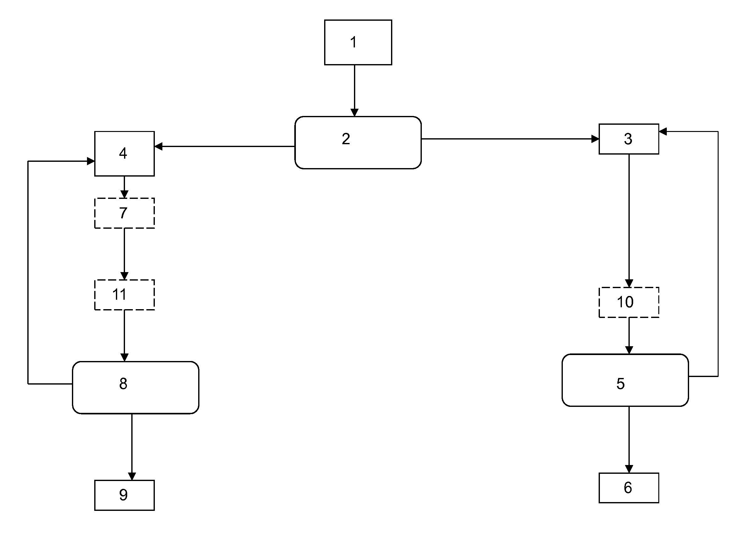
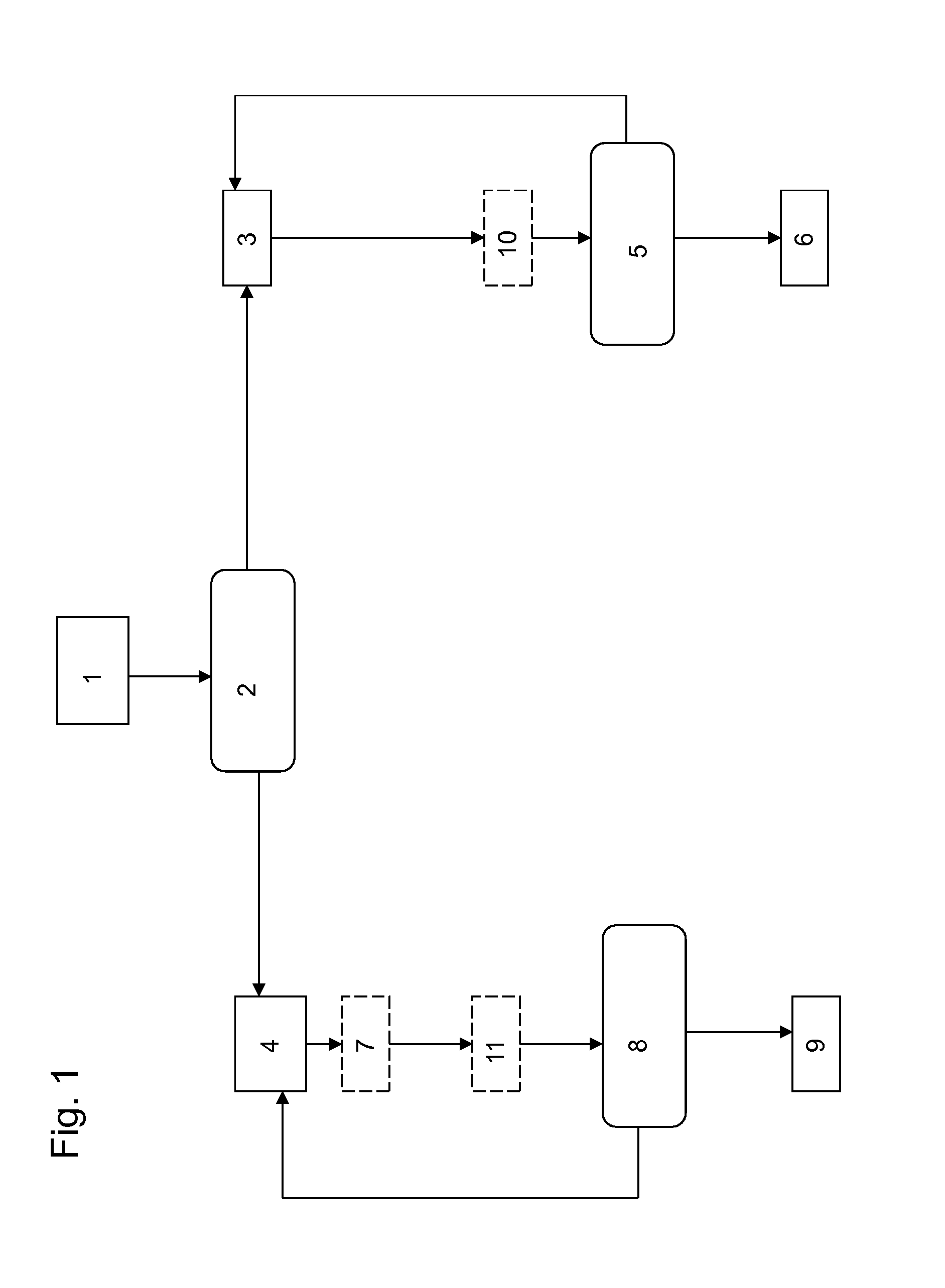
[0027]The method in accordance with the invention commences in block 1, in which it is established that an actuating element has been moved from its idle position into one of its positions of use. In other words, it is established in block 1 whether the parking brake is to be activated.

[0028]It is established in a decision block 2 whether a static parking brake mode or a dynamic parking brake mode is prevailing, which can be detected by means of the rotational speed of the wheels, i.e. using corresponding sensors.

[0029]The two signals “wheel rotation rate” and “actuation of the parking brake” are processed accordingly in block 2, so that a control signal is generated. If a static mode is recognized, the method is continued with block 3. If a dynamic mode is recognized, the method is continued with block 4.

[0030]In the static mode, a signal is generated in block 3, which signal activates the hydraulic pump of the ESP-unit, wherein preferably the maximum hydraulic pressure is generate...


PUM


Abstract

The invention relates to a method for operating a brake device, in particular of a motor vehicle, wherein the brake device comprises a service brake and a mechanical parking brake, wherein the parking brake can be actuated by means of a mechanical actuating element, comprising at least the steps of establishing that the actuating element has been moved from an idle position into a position of use, simultaneously controlling a pressure-increasing element, so that a hydraulic pressure is generated, which hydraulic pressure acts on a brake element that is common with the holding element, blocking the common brake element of the service brake and the parking brake with a mechanical block of the mechanical parking brake.

Description

CROSS REFERENCE TO RELATED APPLICATIONS[0001]This application claims priority to German application number 102012200178.6 filed on Jan. 9, 2012, the entire contents of which are hereby incorporated herein by reference for all purposes.BACKGROUND AND SUMMARY[0002]The present invention relates to a method for operating a brake device, in particular of a motor vehicle, wherein the brake device comprises a service brake and a mechanical parking brake, wherein the parking brake can be actuated by means of a mechanical actuating element.[0003]It is known to provide on motor vehicles dedicated actuating elements for the parking brake such as a hand brake lever or foot lever. The parking brakes concerned are mechanical parking brakes that are connected, for example, by way of a cable pull to the actuating element in the vehicle internal space. The driver actuates the actuating element, i.e. pulls the hand brake lever upwards or depresses the foot lever, as a consequence of which, for exampl...

Claims


Application Information

Patent Timeline
Patent Type & Authority Patents(United States)
IPC IPC(8): B60T8/32B60T13/58B60T13/66F16D63/00
CPCF16D63/00B60T13/588B60T13/662
Inventor TOMCZAK, PETERSCHMID, REINER
Owner FORD GLOBAL TECH LLC
Why Eureka
Try Eureka