Ultrasonic transducer for use in a fluid medium

a transducer and ultrasonic technology, applied in the direction of mechanical vibration separation, instruments, machines/engines, etc., can solve the problems of high coupling loss in the coupling of ultrasonic signals, and achieve the effects of low resistance, high stress, and easy infiltration of media

Inactive Publication Date: 2015-03-24
ROBERT BOSCH GMBH
View PDF20 Cites 5 Cited by
  • Summary
  • Abstract
  • Description
  • Claims
  • Application Information

AI Technical Summary

Benefits of technology

[0011]Besides the at least one electroacoustic transducer element, the transducer core is able to include further elements. In particular, as will be stated in greater detail below, the transducer core is able to include at least one matching element which is equipped to improve an acoustic coupling between the electroacoustic transducer element and the fluid medium. In this context, it may be an impedance-matching element. In optimum fashion, this impedance-matching element has an acoustic impedance which is between the acoustic impedance of the electroacoustic transducer element and the acoustic impedance of the fluid medium, ideally close to the geometric mean of these acoustic impedances. In the case of real ultrasonic transducers and especially in the case of gaseous media, matching elements are also used having other, mostly higher acoustic impedances. The matching element may also include a plurality of materials having different acoustic impedances and / or a material having an acoustic impedance gradient. For possible embodiments of such a matching element, which may be embodied, for example, as a matching layer, we may point out the documents cited above, namely, published German patent application documents DE 10 2007 010 500 A1, DE 10 2007 037 088 A1 and DE 10 2008 055 126.0. The matching elements used in those documents may basically also be used within the scope of the present invention. Moreover, the transducer core may include additional elements. For example, between the optional matching element and the electroacoustic transducer element, at least one compensation element, particularly at least one compensation layer may be provided. Such a compensation element is able to prevent, for instance, the buildup of thermomechanical stresses based on different thermal coefficients of expansion of the electroacoustic transducer element and the matching element, for example, in that a thermal coefficient of expansion is selected for this compensation element which lies between that of the electroacoustic transducer element and that of the matching element. As an example, this compensation element may include at least one adhesive layer. However, other designs are basically also possible.
[0015]By a sealing material one should understand, in this context, basically any material which is able to be applied to the sealing foil in a deformable state, for instance, in a liquid, viscous or pasty or otherwise deformable state. The sealing foil is thus able to adapt itself to the shape of the edge of the foil. The sealing material is also able particularly to penetrate wholly or partially into an interstice between the housing and the edge of the sealing foil, and / or is able to close a gap between an edge of the sealing foil and the housing. By sealing, one should generally understand, in this context, a state in which the inner space is protected by the sealing material at least partially from influences of the fluid medium, such as from chemical effects and / or pressure effects.
[0024]The ultrasonic transducer provided and the sensor system provided have numerous advantages over the known ultrasonic transducers and sensor systems. In particular, an ultrasonic transducer impervious to media may be provided in this way which, in particular, may also be used for flow measuring in internal combustion engines and / or in other aggressive environments. Without the sealing foil named and / or the sealing, the inner space of the ultrasonic transducer, for instance, damping or structure-borne noise decoupling in the ultrasonic transducer, would be exposed to the, at times, aggressive fluid media, for instance, the media contained in a motor vehicle intake tract, such as moisture, oil, exhaust gas components, hydrocarbons, acids and similar aggressive media. For the decoupling of the transducer core from the housing, as a rule, soft silicones are required however, which have low resistance to these media.
[0025]However, a sealing foil by itself is usually exposed to relatively high stresses, especially because of pressure and / or temperature fluctuations. These stresses may be particularly attributed to thermal expansions of materials in the ultrasonic transducer, such as plastic materials. Accordingly, in the usual constructions, the sealing foil is easily infiltrated by media at its edges. On the other hand, by sealing the edges of the foil, the ultrasonic transducer is mechanically stabilized and with respect to its tightness.
[0026]Furthermore, producing the ultrasonic transducer named is also easily managed. The at least one sealing element may be used simultaneously for fastening the ultrasonic transducer in the sensor housing and / or for sealing the ultrasonic transducer from the sensor housing. The simultaneous production of the sealing and the fastening and / or seal considerably simplifies the process sequence during manufacturing.

Problems solved by technology

However, in flow metering in air or other gases, the problem arises that a high acoustical impedance difference will be registered between the material of the electroacoustic transducer element and the air, which leads to high coupling losses in the coupling of ultrasonic signals between the electroacoustic transducer and the gas.
However, the technical challenge comes up in this context that, at the edges of the sealing foil, media continue to be able to penetrate into the inner space of the housing, which can make itself known disadvantageously during flow measurements in internal combustion engines, for example.

Method used


Image

  • Ultrasonic transducer for use in a fluid medium
  • Ultrasonic transducer for use in a fluid medium
  • Ultrasonic transducer for use in a fluid medium

Examples


Embodiment Construction

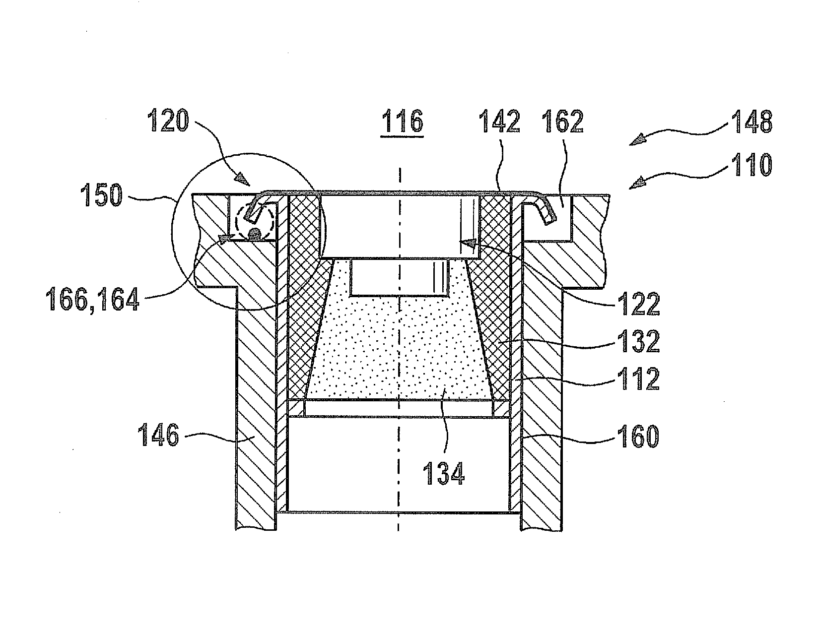
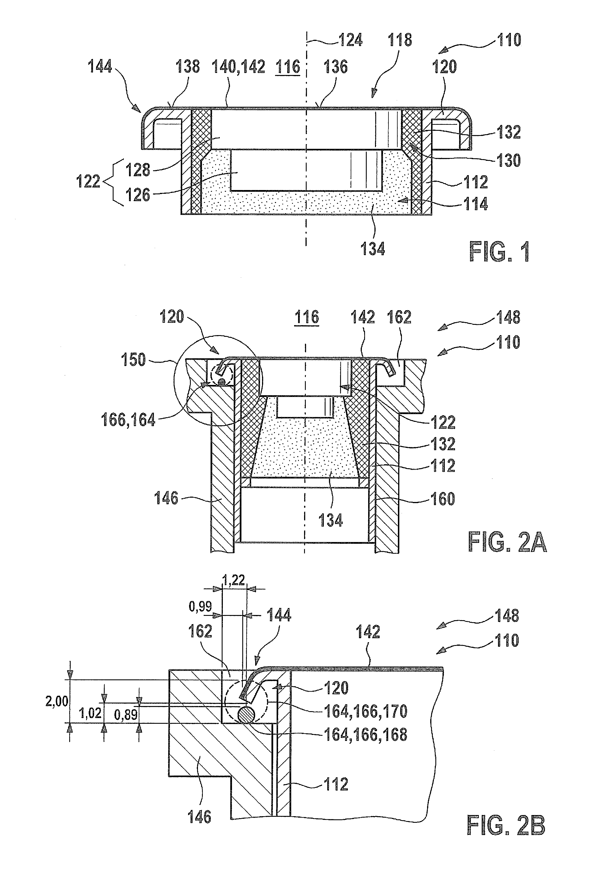
[0031]FIG. 1 shows an exemplary embodiment of an ultrasonic transducer 110 corresponding to the related art, in a sectional representation. Ultrasonic transducer 110 may, for instance, essentially correspond to the ultrasonic transducer shown in German patent application document DE 10 2008 055 126.0. However, other designs are also possible. Ultrasonic transducer 110 includes a housing 112, which is shown only partially in the exemplary embodiment shown. This housing 112 is designed to be sleeve-shaped and has an inner space 114. This inner space 114 in turn has on its side facing fluid medium 116 an opening 118, which may have a circular or polygonal cross section. This opening 118 is surrounded by a housing edge 120 in a circular manner, which in the exemplary embodiment shown is bent over backwards, away from fluid medium 116.

[0032]Within inner space 114, in the exemplary embodiment shown, a transducer core 122 is accommodated, for instance, concentrically to an axis 124 of ultr...


PUM


Abstract

An ultrasonic transducer for use in a fluid medium includes at least one housing having at least one inner space, at least one transducer core accommodated in the inner space, having at least one electroacoustic transducer element. The housing has at least one opening facing the fluid medium. The opening is covered at least partially by at least one sealing foil. An edge of the sealing foil is sealed by at least one sealing material.

Description

BACKGROUND OF THE INVENTION[0001]1. Field of the Invention[0002]The present invention relates to an ultrasonic transducer for use in a fluid medium.[0003]2. Description of Related Art[0004]Various types of ultrasonic transducers for use in fluid media are known from the related art. By ultrasonic transducer one generally means an element that is in a position to emit ultrasonic signals into the fluid medium and / or to pick up ultrasonic signals from the fluid medium and convert them to electrical signals, for example. Such ultrasonic transducers are used, for instance, in ultrasonic flowmeters in industrial process engineering and / or in the automotive field, for example, in flowmeters (ultrasonic flowmeters, UFM), particularly in the intake tract and / or the exhaust tract of internal combustion engines. Examples of such ultrasonic transducers are known from published German patent application documents DE 10 2007 010 500 A1, DE 10 2007 037 088 A1 or from German patent application DE 1...

Claims


Application Information

Patent Timeline
Patent Type & Authority Patents(United States)
IPC IPC(8): G10K11/00G01F23/296G10K9/122G10K9/22
CPCG10K9/122G01F23/296G01F23/2968G10K9/22
Inventor MUELLER, ROLANDHUEFTLE, GERHARDHORSTBRINK, MICHAELLANG, TOBIASRADWAN, SAMIKUENZL, BERNDWANJA, ROLAND
Owner ROBERT BOSCH GMBH
Why Eureka
Try Eureka