
Surgical instrument with stowing knife blade

a surgical instrument and blade technology, applied in the field of surgical instruments with stowing knife blades, can solve the problems of unfavorable stowing of surgical instruments, inability to maneuver, and inability to compact and maneuver known so as to facilitate stowing of the knife, improve surgical clamping and cutting instruments, and reduce the likelihood of unintentional cutting tissu

Active Publication Date: 2015-03-31
INTUITIVE SURGICAL OPERATIONS INC
View PDF32 Cites 1256 Cited by
  • Summary
  • Abstract
  • Description
  • Claims
  • Application Information

AI Technical Summary

Benefits of technology

This patent text describes improved surgical instruments that can clamp and cut tissue more effectively while minimizing the risk of accidental cutting. The instruments use a proximal-to-distal knife movement, which helps to position the knife to reduce the likelihood of unintentionally cutting tissue. The instruments have first and second moving members that move in the same direction at first, and then move relative to each other to facilitate stowing of the knife. The second member is prevented from moving towards the distal end of the instrument to avoid interfering with the rotation of the knife. Overall, this patent describes a new design for surgical instruments that enhances the precision and safety of surgical procedures.

Problems solved by technology

Known surgical clamping and cutting instruments, however, may fail to be both compact and maneuverable.
For example, known surgical staplers may lack maneuverability with respect to multiple degrees of freedom (e.g., Roll, Pitch, and Yaw) and associated desired ranges of motion.
Additionally, surgical clamping and cutting instruments can sometimes fail to fully actuate (e.g., due to a hard obstacle blocking the knife path), potentially leaving a knife blade exposed.
Known surgical clamping and cutting instruments, however, may fail to avoid the potential knife hazard and at the same time be compact and maneuverable.

Method used


Image

  • Surgical instrument with stowing knife blade
  • Surgical instrument with stowing knife blade
  • Surgical instrument with stowing knife blade

Examples


Embodiment Construction

[0060]In the following description, various embodiments of the present invention will be described. For purposes of explanation, specific configurations and details are set forth in order to provide a thorough understanding of the embodiments. However, it will also be apparent to one skilled in the art that the present invention may be practiced without the specific details. Furthermore, well-known features may be omitted or simplified in order not to obscure the embodiment being described.

Minimally Invasive Robotic Surgery

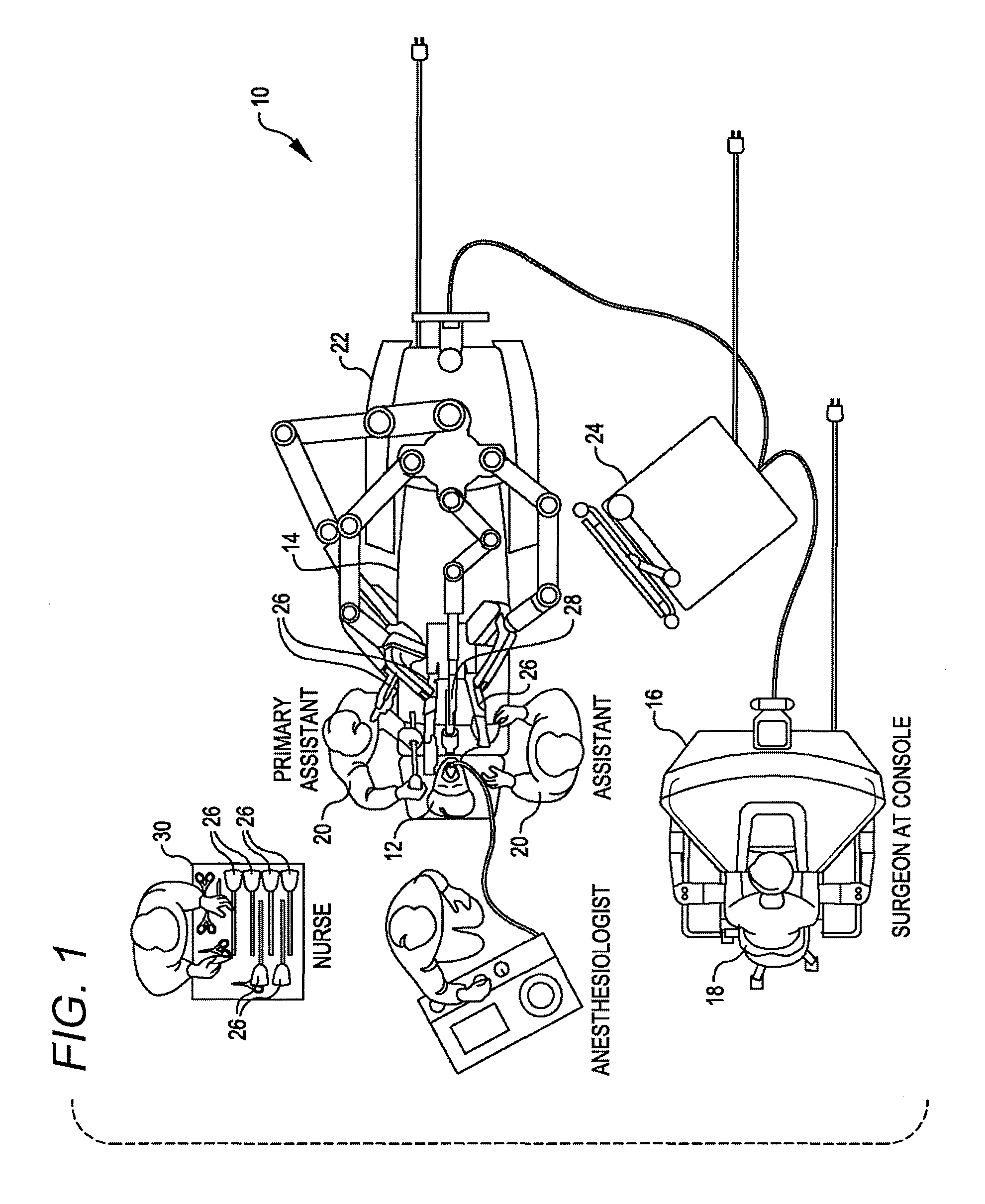
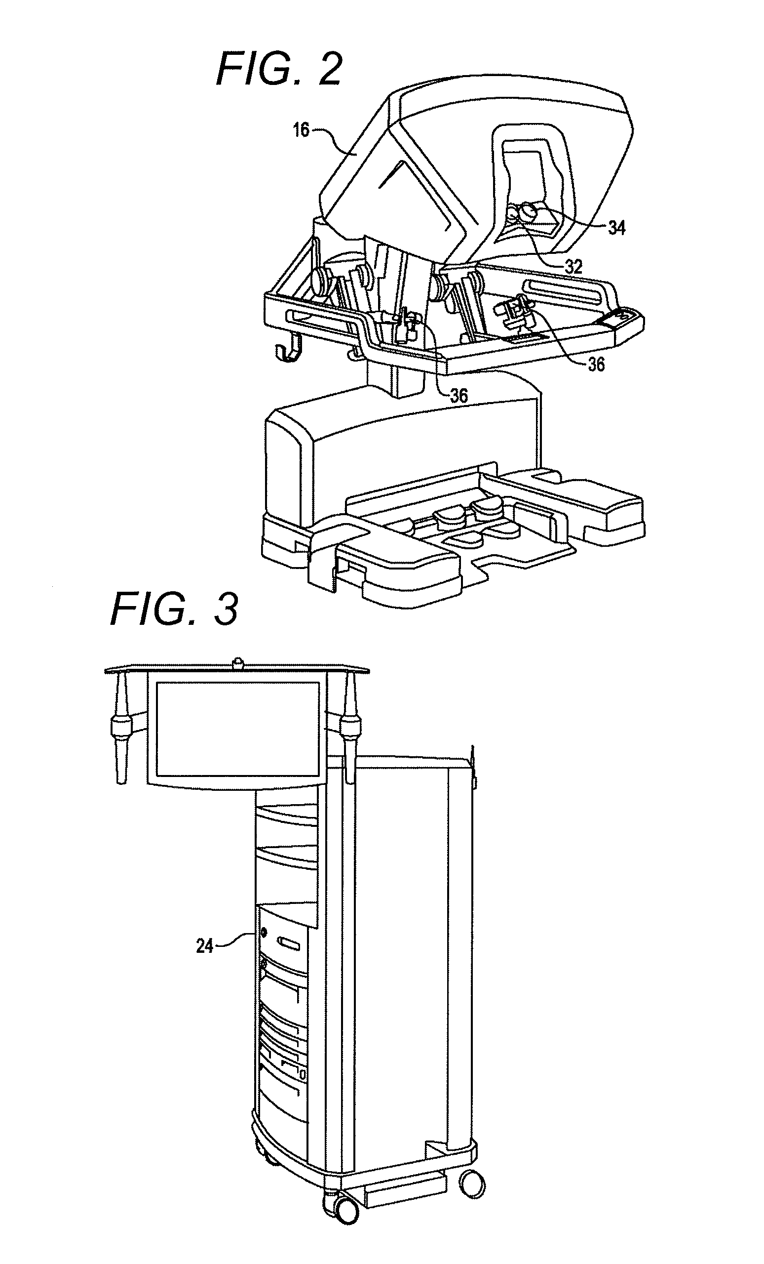
[0061]Referring now to the drawings, in which like reference numerals represent like parts throughout the several views, FIG. 1 is a plan view illustration of a Minimally Invasive Robotic Surgical (MIRS) system 10, typically used for performing a minimally invasive diagnostic or surgical procedure on a Patient 12 who is lying down on an Operating table 14. The system can include a Surgeon's Console 16 for use by a Surgeon 18 during the procedure. One or more Assis...


PUM

PropertyMeasurementUnit
distanceaaaaaaaaaa
rotationaaaaaaaaaa
lengthaaaaaaaaaa

Abstract

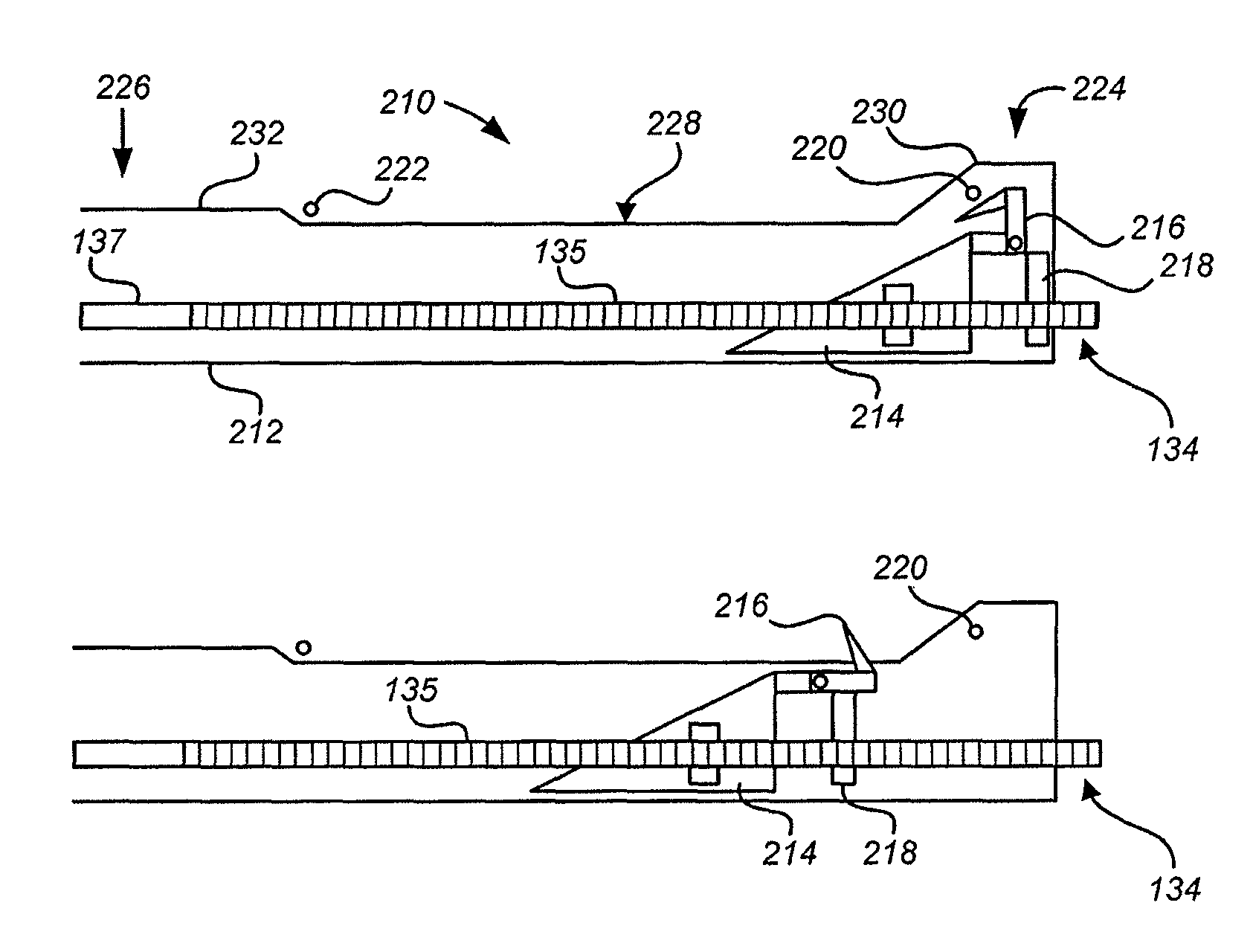
A surgical instrument with a stowing knife blade includes an elongated shaft, an end effector coupled to the shaft and including two opposed jaws, a housing included in one of the jaws, a first member mounted in the housing and movable distally, a knife pivotally coupled with the first member, and a second member. The knife is configured to cut when advanced distally. The first and second members are moved distally at the same rate during a cutting motion of the knife and the second member blocks a rotation of the knife relative to the first member during the cutting motion of the knife. After moving through the first distance, relative movement between the first and second members occurs so as to permit or induce the previously blocked rotation of the knife so that the knife can be stowed.

Description

[0001]This application claims the benefit of U.S. Provisional Application No. 61 / 560,225, filed Nov. 15, 2011, the entirety of which is incorporated by reference herein.BACKGROUND[0002]Minimally invasive surgical techniques are aimed at reducing the amount of extraneous tissue that is damaged during diagnostic or surgical procedures, thereby reducing patient recovery time, discomfort, and deleterious side effects. As a consequence, the average length of a hospital stay for standard surgery may be shortened significantly using minimally invasive surgical techniques. Also, patient recovery times, patient discomfort, surgical side effects, and time away from work may also be reduced with minimally invasive surgery.[0003]A common form of minimally invasive surgery is endoscopy, and a common form of endoscopy is laparoscopy, which is minimally invasive inspection and surgery inside the abdominal cavity. In standard laparoscopic surgery, a patient's abdomen is insufflated with gas, and ca...

Claims


Application Information

Patent Timeline
Patent Type & Authority Patents(United States)
IPC IPC(8): A61B17/068A61B17/072A61B19/00A61B19/02
CPCA61B17/07207A61B17/0686A61B2017/07285A61B2019/481A61B2017/07278A61B2019/025A61B50/13A61B2090/08021A61B17/320016A61B17/072A61B34/30A61B17/295A61B2017/07214A61B2034/252A61B17/068A61B17/115
Inventor WELLMAN, ASHLEYBURBANK, WILLIAMDUQUE, GRANTFLANAGAN, PATRICK
Owner INTUITIVE SURGICAL OPERATIONS INC
Learn More