Vertebral treatment

a technology for vertebrae and treatment, applied in the field of vertebral treatment, can solve the problems of difficult access to the posterior midline section of the s1 segment of the spine, difficult to place a probe in the vertebrae, and difficulty in navigating a probe in the bone, so as to minimize the volume of bone tissue and modulate the bvn with substantial certainty

Inactive Publication Date: 2015-03-31
RELIEVANT MEDSYST
View PDF518 Cites 46 Cited by
  • Summary
  • Abstract
  • Description
  • Claims
  • Application Information

AI Technical Summary

Benefits of technology

[0060]Several embodiments provide a very controlled total heating zone which exists substantially only between the paired electrodes. In accordance with several embodiments, the consequent ability to both modulate the BVN with substantial certainty and to minimize the volume of bone tissue affected by the heating appears to be novel in light of the conventional bone-related technology.
[0061]Accordingly, some embodiments of the invention are advantageous because they allow the clinician to create a sufficiently large heating zone for therapeutically treating the ION (e.g., BVN) without requiring direct access to the ION. Some embodiments of the invention are particularly advantageous because such embodiments: (i) do not require knowing the precise location of the ION, (ii) do not require directly accessing the ION, and / or (iii) have a controlled heating profile that allows a clinician to avoid heating adjacent structures such as the healthy adjacent cancellous bone tissue, the spinal cord or opposing vertebral endplates.

Problems solved by technology

Although accessing the vertebral segments of the spine through the pedicle and into the lateral / anterior section of the body of the vertebra is a primary method of placing a treatment device or neuromodulation device (e.g. a bone cement delivery device, a chemical agent delivery device, and / or an RF probe) into the vertebra, it can be difficult to place a probe in the posterior midline section of the vertebra.
Furthermore, accessing the posterior midline section of the S1 segment of the spine can be difficult with a straight linear access route.
However, due to the varying densities of bone, it can be difficult to navigate a probe in bone and ensure its positioning will be in the posterior (e.g., posterior to the midline) or posterior midline section of the vertebral body.

Method used


Image

  • Vertebral treatment
  • Vertebral treatment
  • Vertebral treatment

Examples


examples

[0282]The following Examples illustrate some embodiments of the invention and are not intended in any way to limit the scope of the disclosure. Moreover, the methods and procedures described in the following examples, and in the above disclosure, need not be performed in the sequence presented.

example i

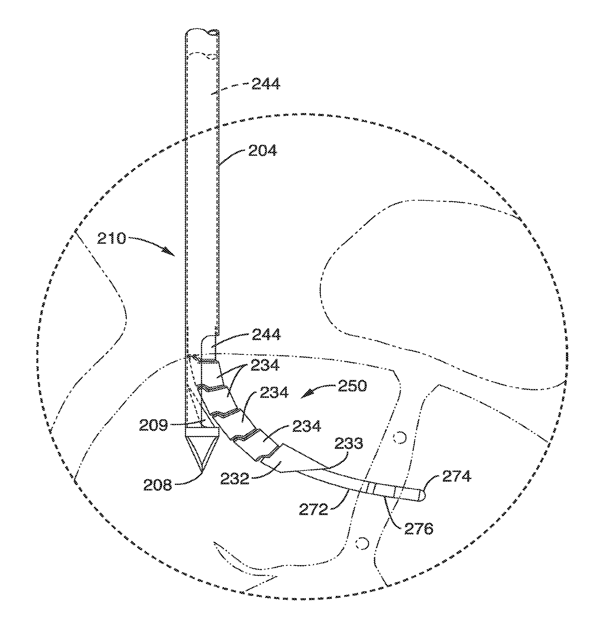
[0283]This example describes an embodiment of a method of use of one of the dual probe embodiments.

[0284]First, after induction of an appropriate amount of a local anesthesia, the human patient is placed in a prone position on the table. The C-arm of an X-ray apparatus is positioned so that the X-rays are perpendicular to the axis of the spine. This positioning provides a lateral view of the vertebral body, thereby allowing the surgeon to view the access of the apparatus into the vertebral body.

[0285]Next, a cannulated stylet comprising an inner stylet and an outer cannula are inserted into the skin above each of the respective pedicles so that the distal tip of each stylet is in close proximity to the respective pedicle.

[0286]Next, the probe is advanced interiorly into the body so that the stylet tips bores through the skin, into and through the pedicle, and then into the vertebral body. The stylet is advanced until the tips reach the anterior-posterior midline of the vertebral bod...

example ii

[0289]This example describes the efficacy of heating a large zone of a vertebral body with an embodiment of a bipolar energy device. In accordance with one embodiment, the testing procedure was performed as follows:

[0290]A pair of probes was inserted into a vertebral body of an ovine animal model so that the tips of the electrodes were located substantially at the midline and separated by about 4 mm. Each electrode had a cylindrical shape, a length of about 20 mm, and an outer diameter of about 1.65 mm (16 gauge) to produce a surface area of about 100 mm2.

[0291]Next, and now referring to FIGS. 47A and 47B, thermocouples 0-14 were placed within the vertebral body at the 15 locations. Thermocouples 0-4 were placed halfway between the electrode tips and were separated by a distance of 2 mm. Thermocouples 5-9 were placed about at the midpoint between the probe tips, and were vertically separated by a distance of 2 mm Thermocouples 10-14 were placed along the distal portion of the probe ...


PUM


Abstract

Methods and systems for modulating intraosseous nerves (e.g., nerves within bone) are provided. For example, the methods and systems described herein may be used to modulate (e.g., denervate, ablate) basivertebral nerves within vertebrae. The modulation of the basivertebral nerves may facilitate treatment of chronic back pain. The modulation may be performed by a neuromodulation device (e.g., an energy delivery device).

Description

CROSS-REFERENCE TO RELATED APPLICATIONS[0001]This application is a continuation of U.S. application Ser. No. 13 / 615,300, filed Sep. 13, 2012, now abandoned, which is a continuation of U.S. application Ser. No. 13 / 612,541, filed on Sep. 12, 2012, now U.S. Pat. No. 8,361,067, which is a continuation-in-part of U.S. application Ser. No. 12 / 683,555, filed on Jan. 7, 2010, now U.S. Pat. No. 8,613,744, which is a continuation-in-part of U.S. application Ser. No. 12 / 566,895, filed on Sep. 25, 2009, now U.S. Pat. No. 8,419,730, which claims priority from U.S. Provisional Application No. 61 / 100,553 filed on Sep. 26, 2008, the content of each of which is incorporated herein by reference in its entirety. U.S. application Ser. No. 12 / 683,555 is also a continuation-in-part of U.S. application Ser. No. 11 / 123,766 filed on May 6, 2005, now U.S. Pat. No. 7,749,218, which is a divisional of U.S. application Ser. No. 10 / 260,879 filed on Sep. 30, 2002, now U.S. Pat. No. 6,907,884, the content of each ...

Claims


Application Information

Patent Timeline
Patent Type & Authority Patents(United States)
IPC IPC(8): A61B18/14A61B17/00A61B17/32A61B17/34A61B17/88A61B18/00A61B18/02A61B18/08A61B18/16A61B18/18A61B18/20A61B18/22A61B19/00A61N1/05A61N5/00
CPCA61B18/148A61B17/3472A61B18/18A61B17/8819A61N5/00A61B17/8805A61B18/02A61B18/16A61B2018/00017A61B2018/00339A61B2018/00434A61B2017/00331A61B17/320068A61B18/082A61B18/1815A61B18/20A61B18/22A61B2017/00867A61B2018/00565A61B2018/00577A61B2018/00589A61B2018/00642A61B2018/0072A61B2018/00791A61B2018/00821A61B2018/1425A61B2018/1807A61B2018/2005A61B2019/2211A61B2019/5236A61N1/0551A61B2034/301A61B2090/374A61B18/1206A61B18/1492A61B2018/126A61B2017/00261A61B2018/00761A61B2218/002A61N7/00A61B18/1487A61B2018/0044A61B2017/320069A61B18/12A61N1/06
Inventor PELLEGRINO, RICHARDPAPINEAU, PAULACROMBIE, JOHN S.PATEL, SAMITRYAN, THOMAS
Owner RELIEVANT MEDSYST
Why Eureka
Try Eureka