
LED-based large area display

a technology of color displays and leds, applied in the direction of fluid pressure measurement, identification means, instruments, etc., can solve the problems of color inconsistencies to appear later, inconvenient manufacturing and calibration, and difficult to make the red and green leds on the panel all individually generate the exact same visual color appearance, etc., to eliminate color drift, eliminate any unpleasant appearance, and eliminate color drift.

Active Publication Date: 2015-03-31
INTEMATIX
View PDF150 Cites 9 Cited by
  • Summary
  • Abstract
  • Description
  • Claims
  • Application Information

AI Technical Summary

Benefits of technology

The patent describes a new way to make LED displays that don't have color blinking or inconsistencies between different panels. They use the same type of blue LEDs, which means they're more likely to be consistent and calibrate well. The LEDs are controlled by a common drive voltage and current, which makes it easier to drive them all. This also means the display looks better, even when it's turned off. The technology allows for a seamless surface that's more aesthetically pleasing than previous LED displays.

Problems solved by technology

However, there are numerous drawbacks with this RGB LED approach to implementing large display panels.
One significant problem is that it is quite difficult to make the red and green LEDs on the panel all individually generate the exact same visual color appearance.
If some of the red and green LEDs produce different shades of red or green color from other red and green LEDs, then this inconsistency in the color performance of the LEDs causes the overall panel to produce unacceptable images.
This color inconsistency may be due to numerous reasons, such as differential thermal performance, and differences in required drive voltages and current of the different LEDs.
Even if the panel produces consistent colors early in its usage period, it is likely that differential aging effects will cause color inconsistencies to appear later in its usage life.
Another problem with the large displays made with individual RGB LEDs is that the red, green, and blue LEDs on the panel are prominently visible as separate LED lights, especially when a viewer is located near to the panel.
This causes the RGB panels to have an aesthetically unpleasing visual appearance to many viewers of the panel.

Method used


Image

  • LED-based large area display
  • LED-based large area display
  • LED-based large area display

Examples


Embodiment Construction

[0021]Throughout this patent specification, like reference numerals are used to denote like parts. For the purposes of illustration only, the following description is made with reference to photoluminescence material embodied specifically as phosphor materials. However, the invention is applicable to any type of photoluminescence material, such as phosphor materials and quantum dots. A quantum dot is a portion of matter (e.g. semiconductor) whose excitons are confined in all three spatial dimensions that may be excited by radiation energy to emit light of a particular wavelength or range of wavelengths. As such, the invention is not limited to phosphor based wavelength conversion materials unless claimed as such.

[0022]Embodiments of the present invention concerns solid-state-based large area color displays. In the context of this patent specification a large area display or lighting panel typically has a width or height of several feet, e.g. at least four feet, and more typically at...


PUM

PropertyMeasurementUnit
heightaaaaaaaaaa
heightaaaaaaaaaa
heightaaaaaaaaaa

Abstract

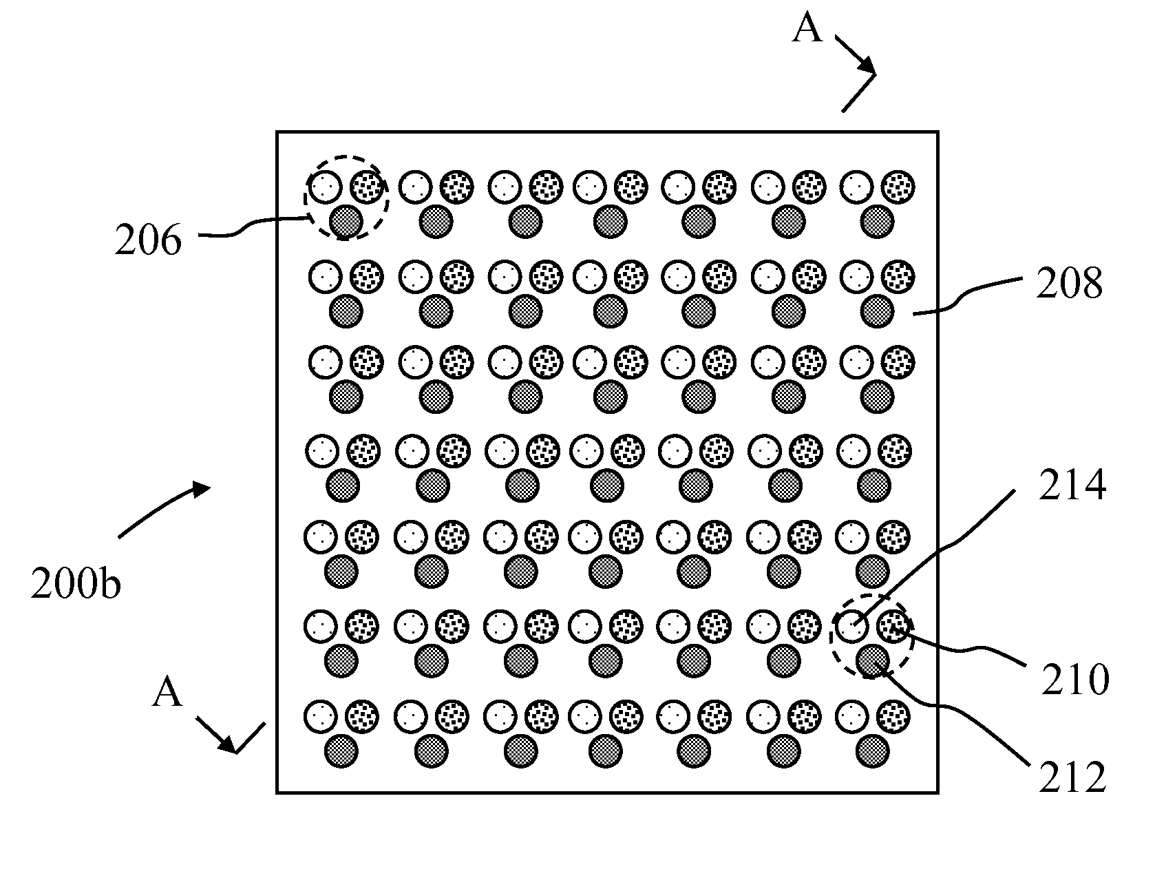
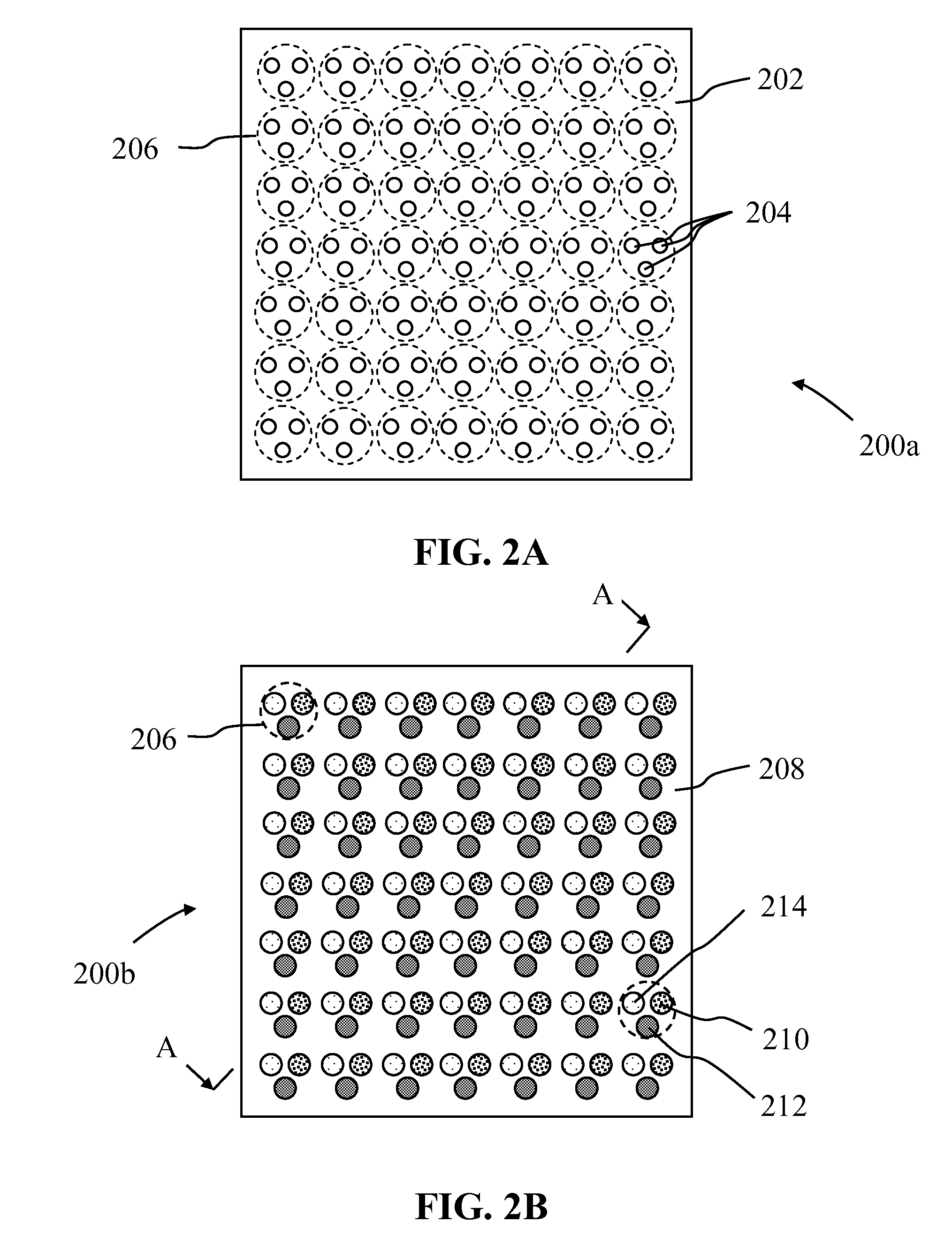
An improved approach is described to implement an LED-based large area display which uses an array of single color solid state lighting elements (e.g. LEDs). In some embodiments, the panel comprises an array of blue LEDs, where each pixel of the array comprises three blue LEDs. An overlay is placed over the array of blue LEDs, where the overlay comprises a printed array of phosphor portions. Each pixel on the PCB comprised of three blue LEDs is matched to a corresponding portion of the overlay having the printed phosphor portions. The printed phosphor portions of the overlay includes a number of regions of blue light excitable phosphor materials that are configured to convert, by a process of photoluminescence, blue excitation light generated by the light sources into green or red and colored light. Regions of the overlay associated with generating blue light comprise an aperture / window that allows blue light to pass through the overlay.

Description

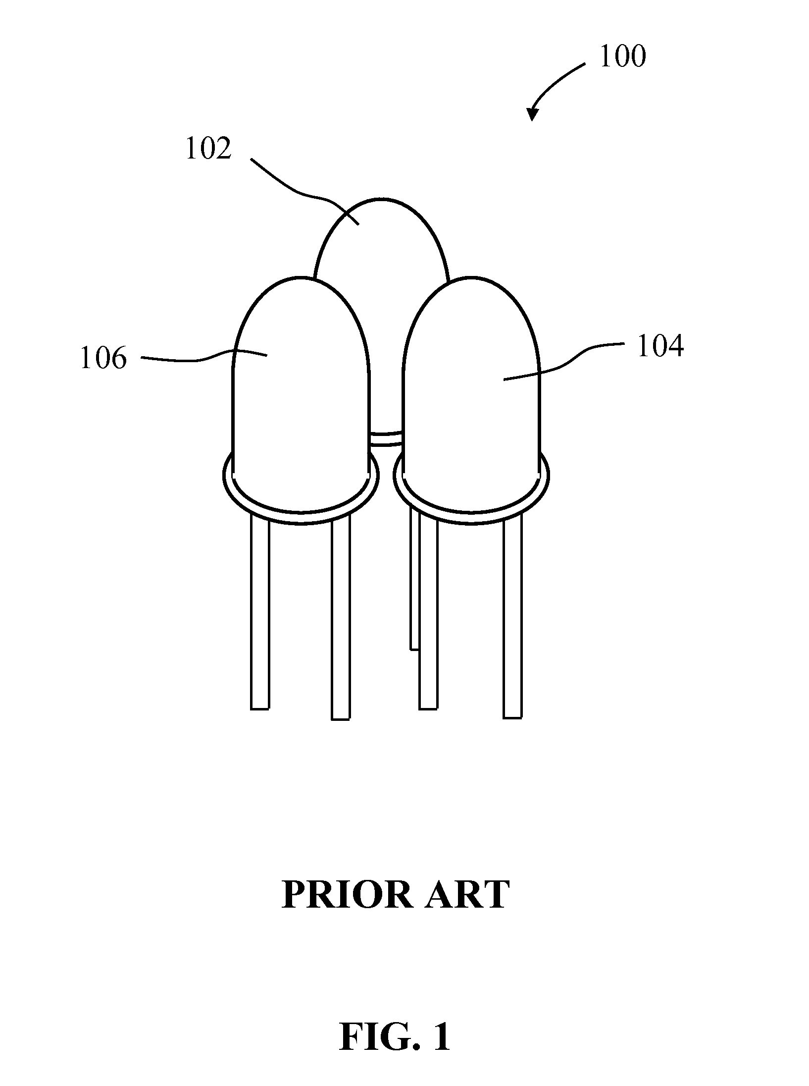
CROSS-REFERENCE TO RELATED APPLICATIONS[0001]The present application claims the benefit of U.S. Provisional Application No. 61 / 671,585, filed on Jul. 13, 2012, which is hereby incorporated by reference in its entirety.BACKGROUND OF THE INVENTION[0002]1. Field of the Invention[0003]This invention relates to large area (format) color displays and lighting panels that incorporate solid-state light emitters such as Light Emitting Diodes (LEDs).[0004]2. Description of the Related Art[0005]There are many types of light generating systems that can be used to implement large format digital color displays and other forms of entertainment lighting products. For example, one common approach is to provide a panel having an array of LEDs lights, where each “pixel” on the panel is composed of three individual red emitting, green emitting, and blue emitting LEDs. FIG. 1 illustrates an example configuration 100 of three LEDs that would be implemented on a panel as a pixel, including a red LED 104, ...

Claims


Application Information

Patent Timeline
Patent Type & Authority Patents(United States)
IPC IPC(8): G01L27/02B82Y20/00G09F9/33H01L27/15
CPCH01L27/156G09F9/33Y10S977/774Y10S977/95B82Y20/00
Inventor EDWARDS, CHARLES
Owner INTEMATIX
Learn More