Method for enhancing depth images of scenes using trellis structures
a technology of depth image and trellis, which is applied in the field of depth image based rendering, can solve the problems of not ideal representation of 3d scene per pixel depth image, and the quality of rendered images is very sensitive, so as to achieve optimal expected quality and reduce artifacts in rendered images
- Summary
- Abstract
- Description
- Claims
- Application Information
AI Technical Summary
Benefits of technology
Problems solved by technology
Method used
Image
Examples
first embodiment
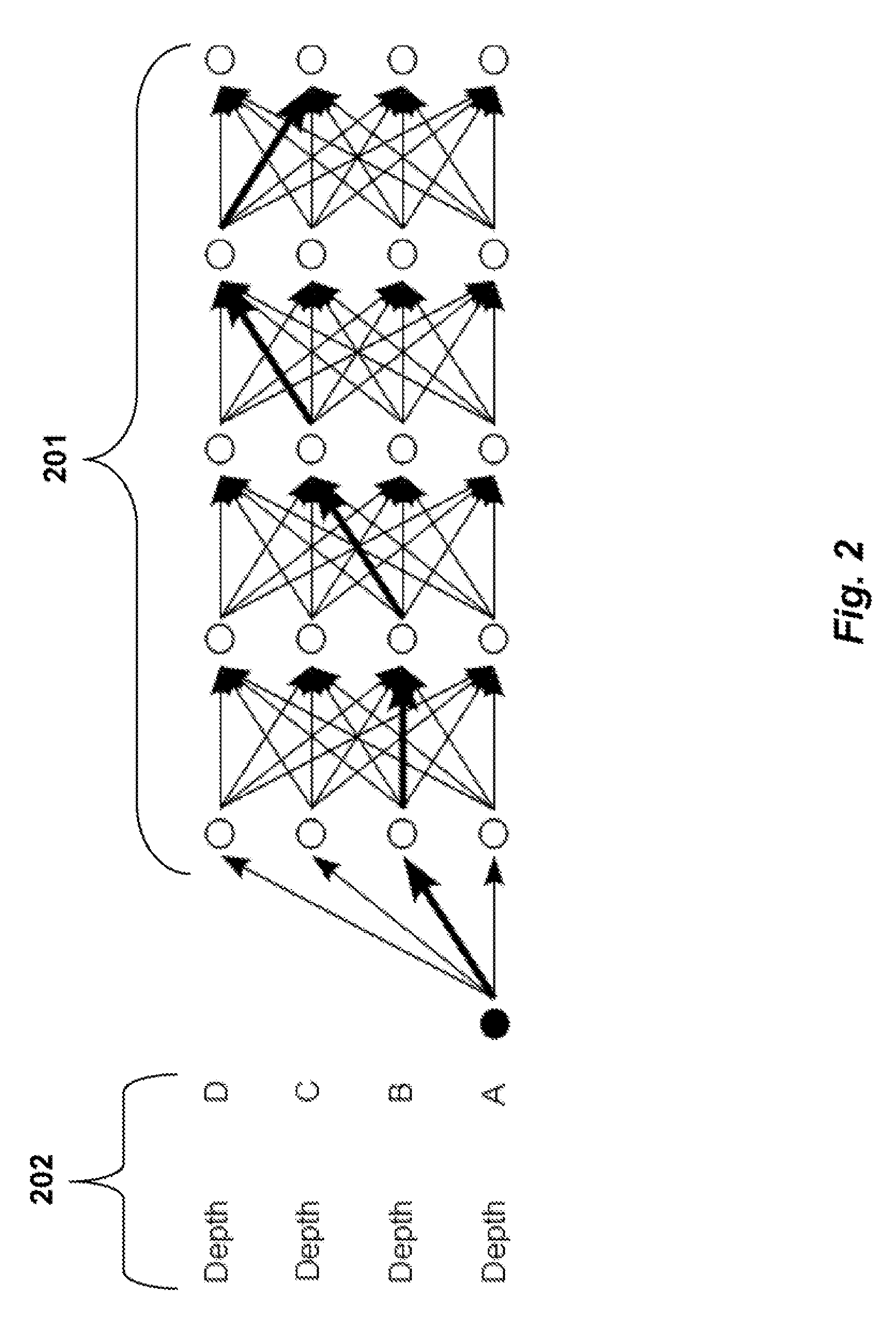
[0051]In the first embodiment as shown in FIG. 7, local optimization is performed with limited complexity. In this embodiment, candidate depth selection does not depend on the selection of the optimal depth candidates from previous pixels. So, the candidate depth assignment and evaluation of the pixels can be performed in parallel. A step-by-step description of this implementation is described below.
[0052]The steps shown in various Figs. can be performed in a processor connected to a memory and input / output interfaces as known in the art. The virtual image can be rendered and outputted to a display device. Alternatively, the steps can be implemented in a system using means comprising discrete electronic components in a video encoder or decoder (codec). More specifically, in the context of a video encoding and decoding system (codec), the method described in this invention for generating virtual images can also be used to predict the images of other views. See for example U.S. Pat. N...
second embodiment
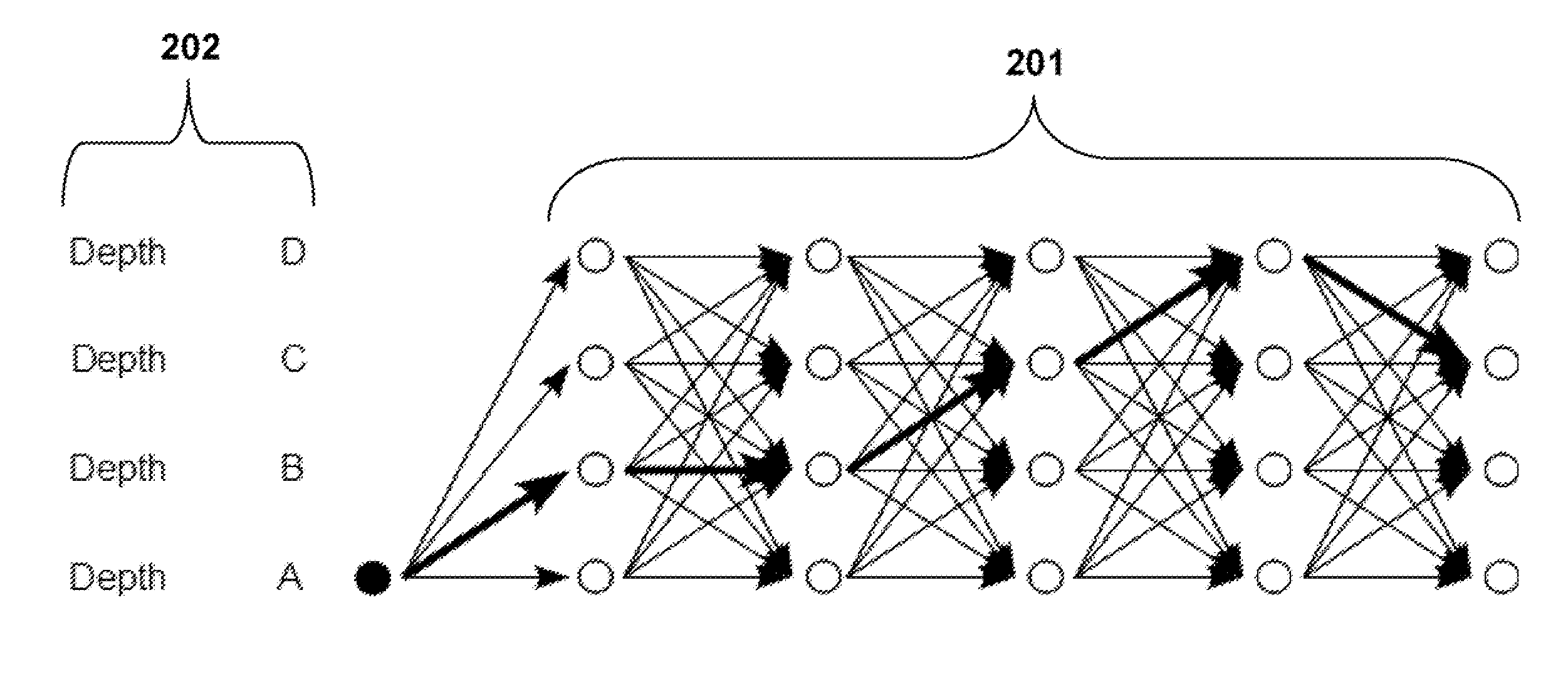
[0060]FIG. 8 shows a second embodiment, which is also a local optimization with limited complexity. In this implementation, the candidate depth assignments in a column of the trellis depend on the optimal depth selection for the immediate previous pixel or column in the trellis. Below is a step-by-step description of this implementation.
[0061]Step 801: we initialize the index i.
[0062]Step 802: Identify candidate depths for pixel i. In this step, we include three depth candidates, which are selected in a similar way as the embodiment shown in FIG. 7. However, when deriving depth B and C, the optimal depths from previous pixels are used, which can be different from what is signaled in the depth image.
[0063]Step 803: Evaluate the cost for each depth candidate of pixel i.
[0064]Step 804: Compare the costs of all the depth candidates and determine the least cost for pixel i.
[0065]Step 805: If there are more pixels not processed in the trellis, then increase i 806 by one, and iterate.
third embodiment
[0066]In the first two embodiments, the optimal depth candidate is selected in the trellis column by column by evaluating a local cost function. In the third embodiment, the optimal path across the trellis, which is a combination of depth candidates from the columns, is determined. A path cost is defined as the sum of the node costs within the path.
[0067]A node can have different costs in different paths. This embodiment is shown in FIG. 9. The procedure has two loops iterating over i and p. The outer loop is over all possible paths, while the inner loop is for all nodes in one possible path.
[0068]For each potential path, we identify 901 and evaluate 902 the candidate depth for the nodes sequentially in the path. The depth candidate assignments are determined as follows. Determine 903 if there are more pixels in the path.
[0069]If the next node locates at row “Depth A,” then the node is set to the depth as signaled in the depth image. If the node locates at row “Depth B,” then we sel...
PUM
 Abstract
Description
Claims
Application Information
 - R&D
- Intellectual Property
- Life Sciences
- Materials
- Tech Scout
- Unparalleled Data Quality
- Higher Quality Content
- 60% Fewer Hallucinations
Browse by: Latest US Patents, China's latest patents, Technical Efficacy Thesaurus, Application Domain, Technology Topic, Popular Technical Reports.
© 2025 PatSnap. All rights reserved.Legal|Privacy policy|Modern Slavery Act Transparency Statement|Sitemap|About US| Contact US: help@patsnap.com


