Microdissection method and information processing system

a microdissection and information processing technology, applied in the field of microdissection methods and information processing systems, can solve the problems of mismatch in workflow, currently not being able to do laser microdissection on samples, and not being able to achieve microdissection on samples, so as to facilitate the control of workflow

Active Publication Date: 2015-03-31
KONINKLIJKE PHILIPS ELECTRONICS NV
View PDF16 Cites 4 Cited by
  • Summary
  • Abstract
  • Description
  • Claims
  • Application Information

AI Technical Summary

Benefits of technology

[0041]providing a user interface for enabling a user to select a data record from the set of data records.
[0042]The information processing system thus facilitates controlling a workflow involving at least two slices cut from, e.g., the same paraffin block. The information processing device may be configured in the described manner by means of both hardware and software, the hardware comprising a memory in which the software has been stored, the software comprising executable instructions for controlling the hardware. The data records may be represented in digital (e.g. binary) form in the memory. More particularly, the slice identifiers and / or the process identifiers may be digital representations of alphanumerical constants. The set of data records may comprise a first data record and a second data record, wherein the process identifier in the first data record and the process identifier in the second data record differ. The user interface may be configured for displaying contents of the selected data record. The user interface may further enable the user to modify the data records in the set of data records and / or to add new data records to the set of data records, and / or to remove data records from the set of data records. The information processing system may comprise a computer, e.g. a personal computer, or a computer network. The information processing system may comprise input means and output means. The input and output means may comprise, for example, at least one of the following: a keyboard, a mouse, a trackball, voice recognition means, a monitor such as a liquid crystal display, and sound output means. The input means and the output means may be integrated in the processing system or form distinct units operatively coupled to the information processing system. The user interface may be implemented by software for controlling the input means and the output means such that the user may exchange information with the information processing system. The information processing system may comprise a memory carrying the set of process identifiers, the set of data records, and the software for controlling the user interface. The memory is not necessarily provided by a single physical unit, but may comprise several distinct memories. A distinct memory may be provided by, for example, a magnetic data carrier, such as a hard disk, or an optical data carrier such as a Compact Disk (CD), Digital Versatile Disk (DVD), or a flash memory.
[0059]The set of data records may indicate, for at least some of the slices indicated by the slice identifiers, an order corresponding to the order in which the at least some slices were arranged before being cut from the object. For example, a number could be included in each or at least some of the data records such that the first slice that was cut from the object is numbered 1, the next slice that was cut is numbered 2, and so on. This may help finding data records relating to adjacent slices. These numbers, together with information about a thickness of each of the adjacent slices, could also be used for generating a three-dimensional image of the object. The number relating to a particular slice and indicating the place previously occupied by the slice in the object may be integrated in the slice identifier or form another entry of the data record. Additionally or alternatively, a data record may contain an entry pointing to another data record, e.g. to the data record of an adjacent slice. Also, information indicating a pair of slices could be added to the data records. This may be useful in order to specify a pair of slices that is intended to be used for defining a colour transformation between colours associated with a first staining method and with a second staining method, respectively. An example of a colour transformation method has been presented by the applicant in a previous application. A pair of slices may, for example, be indicated by a first pointer in a first data record, the first pointer pointing to a second data record, and / or by a second pointer in the second data record, the second pointer pointing to the first data record.
[0082]determining from the region of interest in the second image a region of interest in the second slice.The region of interest in the second slice may thus be derived from the region of interest in the first image. Alternatively a region of interest could be defined directly in the second image and from it the corresponding region of interest in the second slice can be determined. However, the first slice being covered by a cover slip, it may be expected that, depending on the equipment used, the first slice can be imaged more conveniently and possibly more accurately. There may also be situations in which the second slice is produced only after the first slice has been examined and the region of interest has been defined.

Problems solved by technology

A problem standing in the way of more widespread adoption of laser microdissection in the general pathology practice is the fact that current microdissection systems are not matched with the existing pathology workflow.
It is currently not possible to do laser microdissection on samples that are used for normal diagnosis due to the presence of the cover slip on the sample.
This mismatch in workflow might further increase with the introduction of digital pathology since the pathologist will then no longer handle any physical slides.

Method used


Image

  • Microdissection method and information processing system
  • Microdissection method and information processing system
  • Microdissection method and information processing system

Examples


Embodiment Construction

[0108]Unless specified otherwise, identical or similar reference numerals appearing in different Figures label identical or similar components.

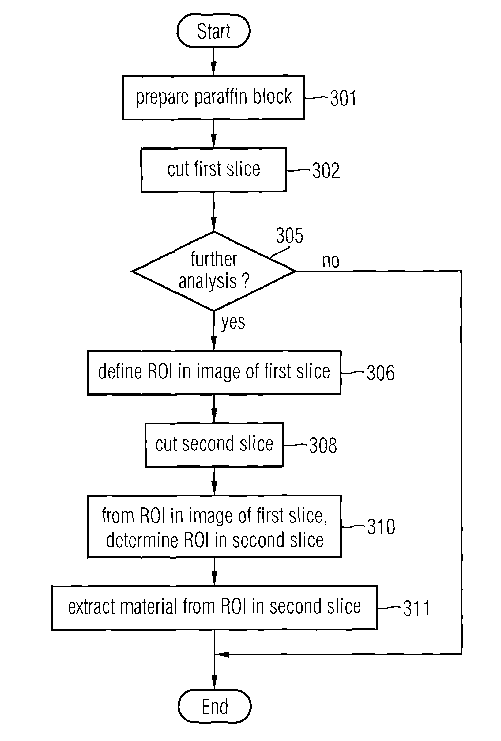
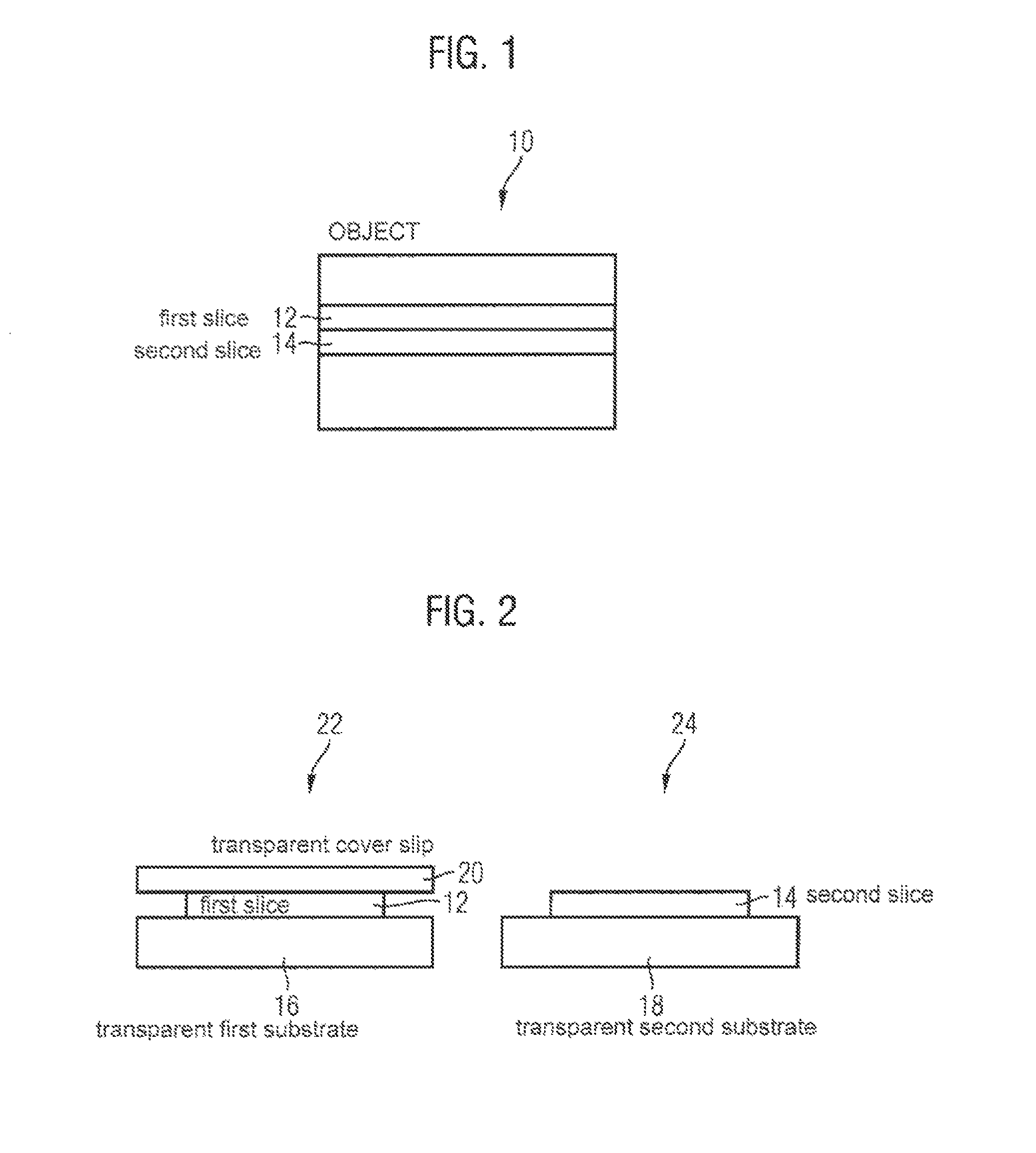
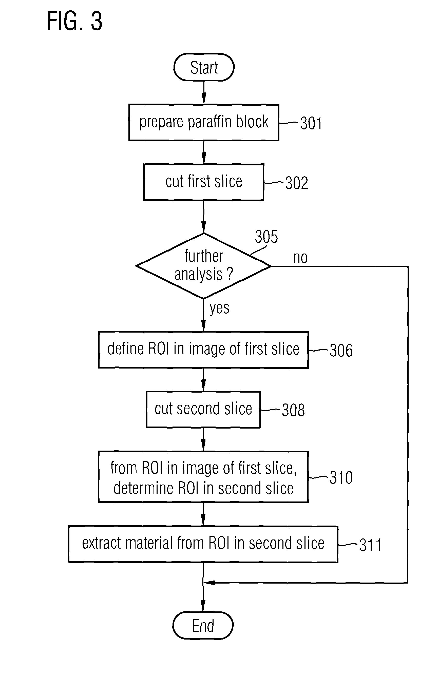
[0109]Shown in FIG. 1 is a schematic side view of a paraffin block 10 comprising biological material, for example, one or more tissue samples, or individual cells. The block 10 comprises a first layer 12 and an adjacent second layer 14 which are destined to be cut from the block to form a first slice 12 and second slice 14, respectively. The first layer 12 and the second layer 14 may alternatively be non-adjacent layers of the block 10 separated by a distance sufficiently short for the two layers 12, 14 to have similar features. More precisely, the two layers 12, 14 are sufficiently near each other for a feature of interest in the block 10 to extend through both layers 12, 14. It is noted that the layers 12, 14 are merely conceptual. They do not need to be defined by any morphological features of the block; rather, they are defined a posterio...


PUM


Abstract

A method for use in biology, histology, and pathology includes providing a digital first image of a first slice of an object having biological material; generating a digital second image of a second slice of the object; determining a region of interest in the second image based on a region of interest in the first image; determining a region of interest in the second slice based on the region of interest in the second image; and extracting material from the region of interest in the second slice.

Description

FIELD OF THE INVENTION[0001]In a first aspect, the invention relates to a method for use in biology, histology and pathology.[0002]In a second aspect, the invention relates to a system for use in biology, histology and pathology.[0003]In a third aspect, the invention relates to a data carrier.[0004]In a fourth aspect, the invention relates to an information processing system for use in biology, histology and pathology.BACKGROUND OF THE INVENTION[0005]A pathologist has a central role in the diagnostic part of the care cycle. When a tissue sample is taken from a patient during a biopsy, it is usually the pathologist who makes a final diagnosis as to the nature and gravity of the disease (mostly cancer related), by microscopic inspection of the tissue and cells from the biopsy.[0006]A microscope slide containing material from a biopsy is typically prepared in several steps as follows. First, the material is usually placed in formalin for fixation and subsequently processed into a paraf...

Claims


Application Information

Patent Timeline
Patent Type & Authority Patents(United States)
IPC IPC(8): G06K9/00G06T7/00
CPCG06T7/0014G06T2207/10056G06T2207/20104G06T2207/30024G01N1/04G01N1/06
Inventor VAN DIJK, ERIK MARTINUS H. P.STALLINGA, SJOERD
Owner KONINKLIJKE PHILIPS ELECTRONICS NV
Why Eureka
Try Eureka