
Secured optical communications using quantum entangled two-photon transparency modulation

a technology of quantum entangled photon transparency and secure optical communication, applied in electromagnetic transmission, electrical equipment, transmission, etc., can solve the problem of not being preferred in free-space communications, particularly communications in military systems

Active Publication Date: 2015-03-31
THE UNITED STATES OF AMERICA AS REPRESENTED BY THE ADMINISTATOR OF NAT AERONAUTICS & SPACE ADMINISTATOR
View PDF11 Cites 6 Cited by
  • Summary
  • Abstract
  • Description
  • Claims
  • Application Information

AI Technical Summary

Benefits of technology

This patent describes an optical communications system that uses entangled-photon spectroscopy for secure communications. The system generates pairs of quantum entangled photons and modulates the delay time between them to encode information. The encoded photons are then transmitted through an optical network to a receiver where the photons are absorbed and fluorescence emitted at a specific wavelength. The system is designed to be highly secure, as it does not require a temporal coincidence gate for optical communication. The technical effects of this patent include improved security and efficiency in optical communications.

Problems solved by technology

The challenge of this cryptographic technique, however, is that any practical implementation may require coincidence-count, post-processing with a separated and secondary data transmission through conventional channels, such as through physical wiring or another wireless network.
While this technique may be suitable for fiber-optic communications, it may not be preferred in free-space communications, particularly communications in military systems.
Although this technique may use entangled coincident photon pairs over an identical optical path, it still requires two independent single photon detectors and a temporal coincidence gate to extract transmitted data.

Method used


Image

  • Secured optical communications using quantum entangled two-photon transparency modulation
  • Secured optical communications using quantum entangled two-photon transparency modulation
  • Secured optical communications using quantum entangled two-photon transparency modulation

Examples


Embodiment Construction

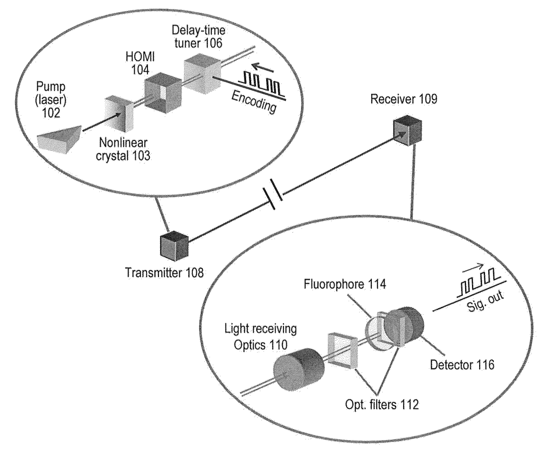
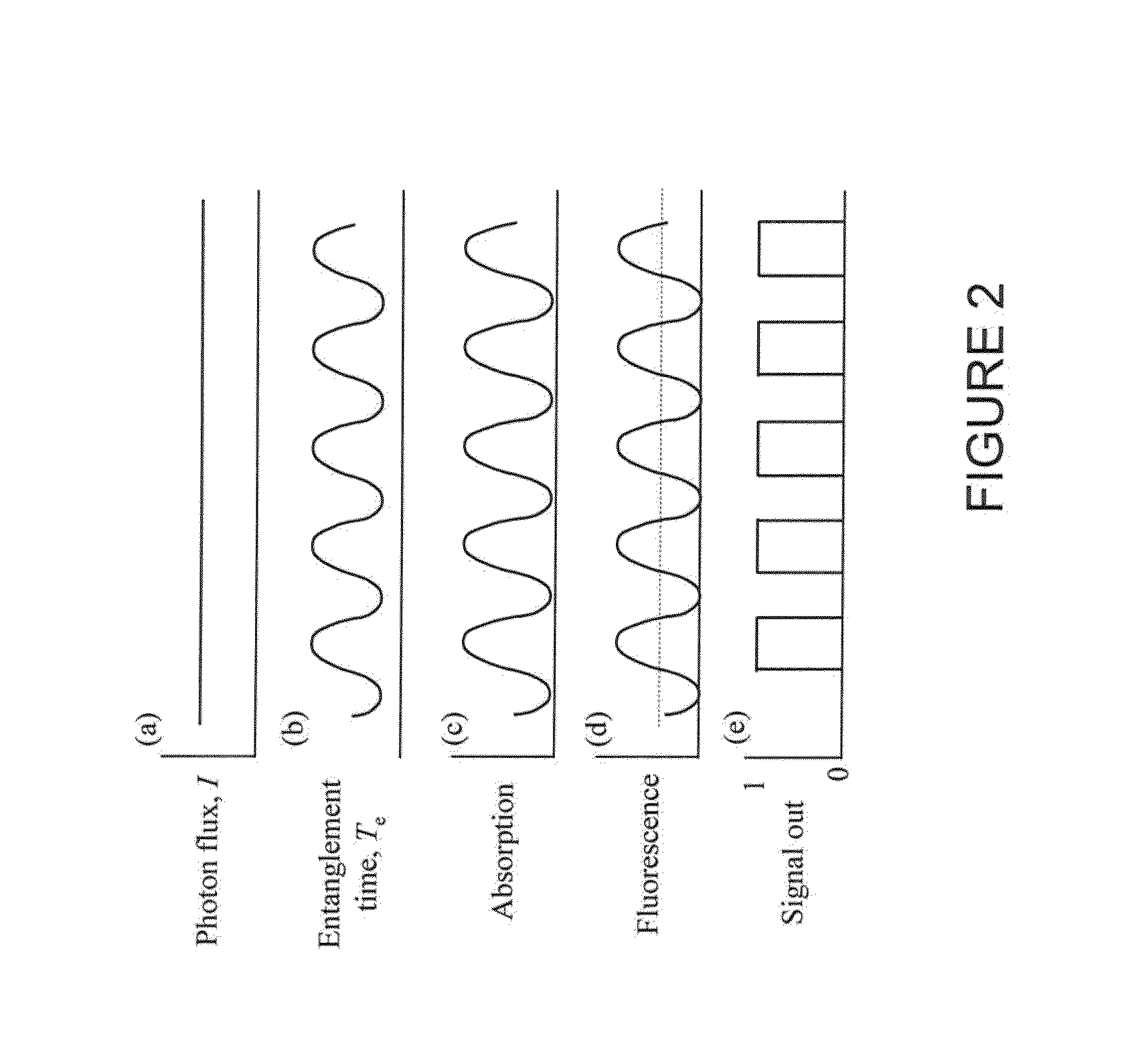
[0014]In an embodiment of the present invention, optical signals may be coded by tuning or modulating delay time (fourth-order coherence) between pairs of entangled twin photons. The photon pairs may be absorbed by a molecular fluorescer followed by corresponding fluorescent optical emissions at a certain wavelength. The fluorescent optical emissions may then be detected by a photon detector. An example of the molecular fluorescer may be a specially synthesized fluorophore. A molecular absorber may act as a coincidence counter for an entangled photon pair. Thus, the quantum fourth-order interference, that is entanglement, is explicitly met in an embodiment of the invention without a use of a pair of detectors connected with coincident circuit.

[0015]FIG. 1 illustrates an implementation of an optical communication using quantum entangled-photon transparency (absorption) modulation spectroscopy. Pairs of quantum entangled photons may be generated via nonlinear optical process, such as ...


PUM


Abstract

A system and method is disclosed wherein optical signals are coded in a transmitter by tuning or modulating the interbeam delay time (which modulates the fourth-order coherence) between pairs of entangled photons. The photon pairs are either absorbed or not absorbed (transparent) by an atomic or molecular fluorescer in a receiver, depending on the inter-beam delay that is introduced in the entangled photon pairs. Upon the absorption, corresponding fluorescent optical emissions follow at a certain wavelength, which are then detected by a photon detector. The advantage of the disclosed system is that it eliminates a need of a coincidence counter to realize the entanglement-based secure optical communications because the absorber acts as a coincidence counter for entangled photon pairs.

Description

FIELD OF THE INVENTION[0001]The present invention relates to a method and architecture for secure optical communications using quantum entangled photon transparency modulation spectroscopyBACKGROUND OF THE INVENTION[0002]Free-space optical technologies may be used as a means of ground, airborne and space-based digital communications and surveillance because of the cost-effectiveness, high-bandwidth and / or enhanced security associated with these technologies. Typically, commercially available optical communications systems may use near-infrared (NIR) lasers to provide a direct point-to-point, high-speed link through the atmosphere, over several kilometers, with a large available bandwidth. Optical communications based on non-linear and quantum optics have been proposed and developed to provide virtually unbreakable security during data transfer. Among these techniques are interferometric communications and retro-modulation communications. These techniques typically rely on photon flu...

Claims


Application Information

Patent Timeline
IPC IPC(8): H04B10/11H04B10/70
CPCH04B10/70
Inventor KOJIMA, JUNNGUYEN, QUANG-VIETLEKKI, JOHN
Owner THE UNITED STATES OF AMERICA AS REPRESENTED BY THE ADMINISTATOR OF NAT AERONAUTICS & SPACE ADMINISTATOR
Learn More