Unlock instant, AI-driven research and patent intelligence for your innovation.

Method and system for optimizing fuel delivery to a fuel injected engine operating in power mode

a technology of power mode and fuel injection engine, which is applied in the direction of electrical control, process and machine control, etc., can solve the problems of not optimizing engine performance, unable to achieve optimal gains, and operation of a particular engine at a particular time may not closely match the conditions which were used, so as to achieve convenient modification and optimize fuel delivery

Inactive Publication Date: 2015-03-31
DOBECK MICHAEL V +1
View PDF31 Cites 2 Cited by
  • Summary
  • Abstract
  • Description
  • Claims
  • Application Information

AI Technical Summary

Benefits of technology

The patent describes a way to modify an existing engine to improve fuel delivery and performance without needing to replace the entire system or add extra sensors. This makes it easier to modify the engine for better performance without additional costs.

Problems solved by technology

On the other hand, the engine's performance is still not optimized because during Power Mode the A / F ratio is determined from the fuel maps.
The operation of a particular engine at a particular time may not closely match the conditions which were used to generate the fuel tables.
In this regard, the open-loop operation of the engine during Power Mode does not ensure that the engine control is varied based upon operating conditions to maximize engine performance.
A problem with these modification products is that optimal gains can often only be realized with associated modifications to the OEM fuel delivery system.
In particular, when a consumer makes an engine modification, such as a modification to the intake or exhaust system that goes beyond the OEM fuel system parameters, performance and functionality of the engine can suffer if associated changes are not made to the engine control system.
However, such a modification has various drawbacks.
These sensors can themselves be expensive and they can be expensive to install and maintain.

Method used


Image

  • Method and system for optimizing fuel delivery to a fuel injected engine operating in power mode
  • Method and system for optimizing fuel delivery to a fuel injected engine operating in power mode
  • Method and system for optimizing fuel delivery to a fuel injected engine operating in power mode

Examples


Embodiment Construction

[0023]In the following description, numerous specific details are set forth in order to provide a more thorough description of the present invention. It will be apparent, however, to one skilled in the art, that the present invention may be practiced without these specific details. In other instances, well-known features have not been described in detail so as not to obscure the invention.

[0024]One embodiment of the invention is a method and system for optimizing fuel delivery to an engine. In one embodiment the method and system have particular applicability to operation of an engine in a Power Mode. Preferably, the method and system of the invention deliver an amount of fuel to an engine to optimize engine speed.

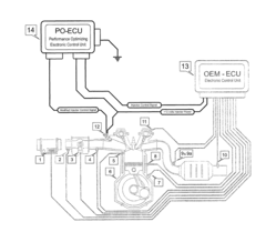
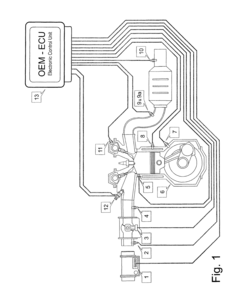
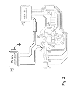
[0025]One aspect of the invention is a method and system which modify the operation of an engine which is controlled by an existing original equipment manufacturer (OEM) engine control unit (ECU), and preferably one which controls the amount of fuel delivered to the engine...


PUM


Abstract

A method and system are provided for optimizing fuel delivery to an internal combustion engine. The method and system have particular applicability to an engine having a base or OEM engine control unit (ECU) which outputs fuel injector control signals. In accordance with the method, when the engine is operating in one or more modes, such as a Power Mode, the amount of fuel delivered to the engine is modified, such as by changing the duration of the fuel injector control signals with a secondary ECU. The control signals are modified based on engine speed, and thus in direct relation to engine performance.

Description

RELATED APPLICATION DATA[0001]This application claims priority to U.S. Provisional Application Ser. No. 61 / 375,430, filed Aug. 20, 2010.FIELD OF THE INVENTION[0002]The present invention relates to methods and devices for controlling the rate of delivery of fuel to an internal combustion engine.BACKGROUND OF THE INVENTION[0003]The overall adaptability, functionality and viability of an internal combustion engine is dependent upon the ability to precisely provide the correct air / fuel (“A / F”) ratio that is best suited for the varying operating conditions of the engine. The current state of the art of engine fuel management comprises various forms of computer controlled electronic fuel injection systems. While the use of fuel injection systems generally results in improved engine performance as a result of better A / F mixing and control (such as compared to carbureted engines), the development of computer controlled fuel injection and its almost universal use was driven by the need to co...

Claims


Application Information

Patent Timeline
Patent Type & Authority Patents(United States)
IPC IPC(8): F02D41/30F02D41/26
CPCF02D41/266F02D41/30F02D2200/101F02D2400/11
Inventor DOBECK, MICHAEL V.MACDONALD, ANDREW M.
Owner DOBECK MICHAEL V