Heating or cooling system featuring a split buffer tank

a technology of heating or cooling system and buffer tank, which is applied in the direction of energy-efficient heating/cooling, heating fuel, sustainable buildings, etc., can solve the problems of loss of high-efficiency boiler during continuous operation, unsolved, and forced to look the other way

Active Publication Date: 2015-04-07
BERRIO DENERING
View PDF27 Cites 13 Cited by
  • Summary
  • Abstract
  • Description
  • Claims
  • Application Information

AI Technical Summary

Benefits of technology

[0034]iv) a pressure release check valve hydraulically connecting a hot face of the disk with a warm face of the disk in order to eliminate pressure differential between the hot and warm sections of the tank that may arise from a make-up fluid connection on the split buffer tank;
[0035]f) the guide bar, which is a center guide squared bar to guide the separation disk up and down along the split buffer tank and to prevent rotation of the disk from causing misalignment of the warm-side bypass with the hot outlet (8), or the hot-side bypass with the warm outlet (11), at an edge of the separation disk, the disk being displaceable up and down along the center guide bar to allow hot and warm fluid accumulation during thermal recharging and discharging of the split buffer tank;
[0037]h) the set of counterweight plates balancing buoyancy of the separation disk to make the separation disk effectively weightless when placed in the fluid medium inside the split buffer tank;
[0038]i) a top position disk stopper to limit displacement of the disk when going to the top position lining up the warm-side bypass with the hot outlet;
[0039]j) a bottom position disk stopper to limit displacement of the disk when going to the bottom position, lining up the hot side bypass with the warm outlet;
[0041]l) a pressurized fluid make-up & air vent connection to maintain continuous fluid supply to the system and to allow for allocation of air vent equipment in association with the split buffer tank.

Problems solved by technology

However, one issue remains unsolved.
That is, the loss of the boiler high efficiency during continuous operation due to the water mixing inside the tank.
But with no solution on hand, they were forced to look the other way.
Flow patterns in the buffer are chaotic and unpredictable with limited opportunities for creating stratification conditions.
From a design stand point this may lead to uneconomical alternatives such as having a much bigger diameter for piping inlet / outlet connections, otherwise designed with acceptable velocity of 2.1±0.9 m / s (7±3 ft / s) for normal liquid service applications, with maximum velocity of 2.1 m / s (7 ft / s) at piping discharge points.
Perhaps even requiring a buffer tank with oversize uneconomical dimensions in diameter and / or height.
As flow pattern and temperature of the mix evolve over time, the rising temperature of the water / brine will increasingly hamper its ability to quickly regain thermal energy when recirculating through the boiler, resulting in longer less efficient runs with increasingly unnecessary consumption of energy resources (See FIG. 6).
This in turn will force chimney gases to escape the boiler without fully rendering their caloric load.
Currently buffer technology has not corrected the problems created with usual configurations such as the one on FIG. 4 (and the like); and as a result, its usage just exacerbate the sub-utilization of condensing boilers in boiler / buffer / systems that ONLY occasionally allow condensation to occur.

Method used


Image

  • Heating or cooling system featuring a split buffer tank
  • Heating or cooling system featuring a split buffer tank
  • Heating or cooling system featuring a split buffer tank

Examples


Embodiment Construction

1. General Character of the invention

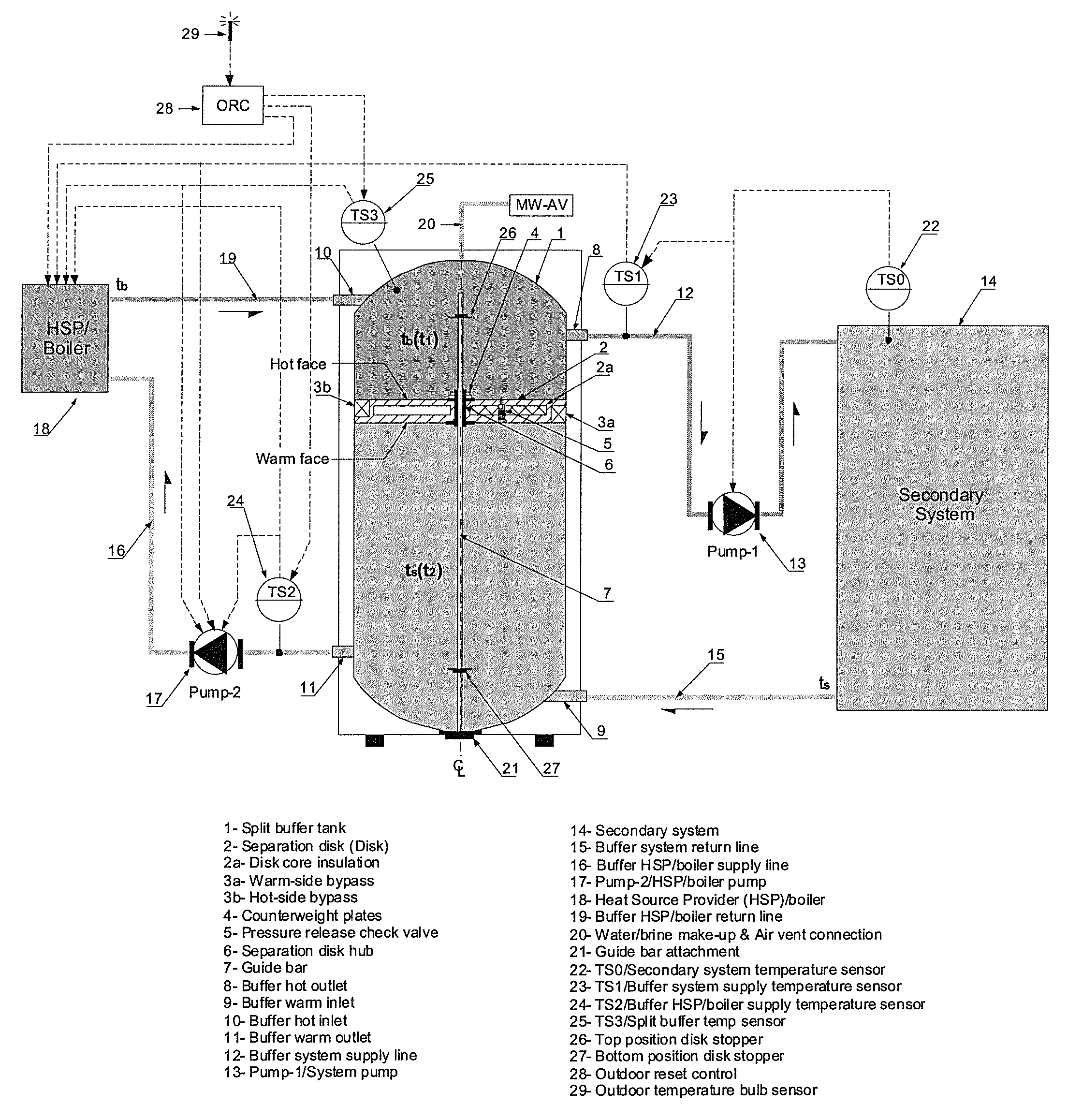
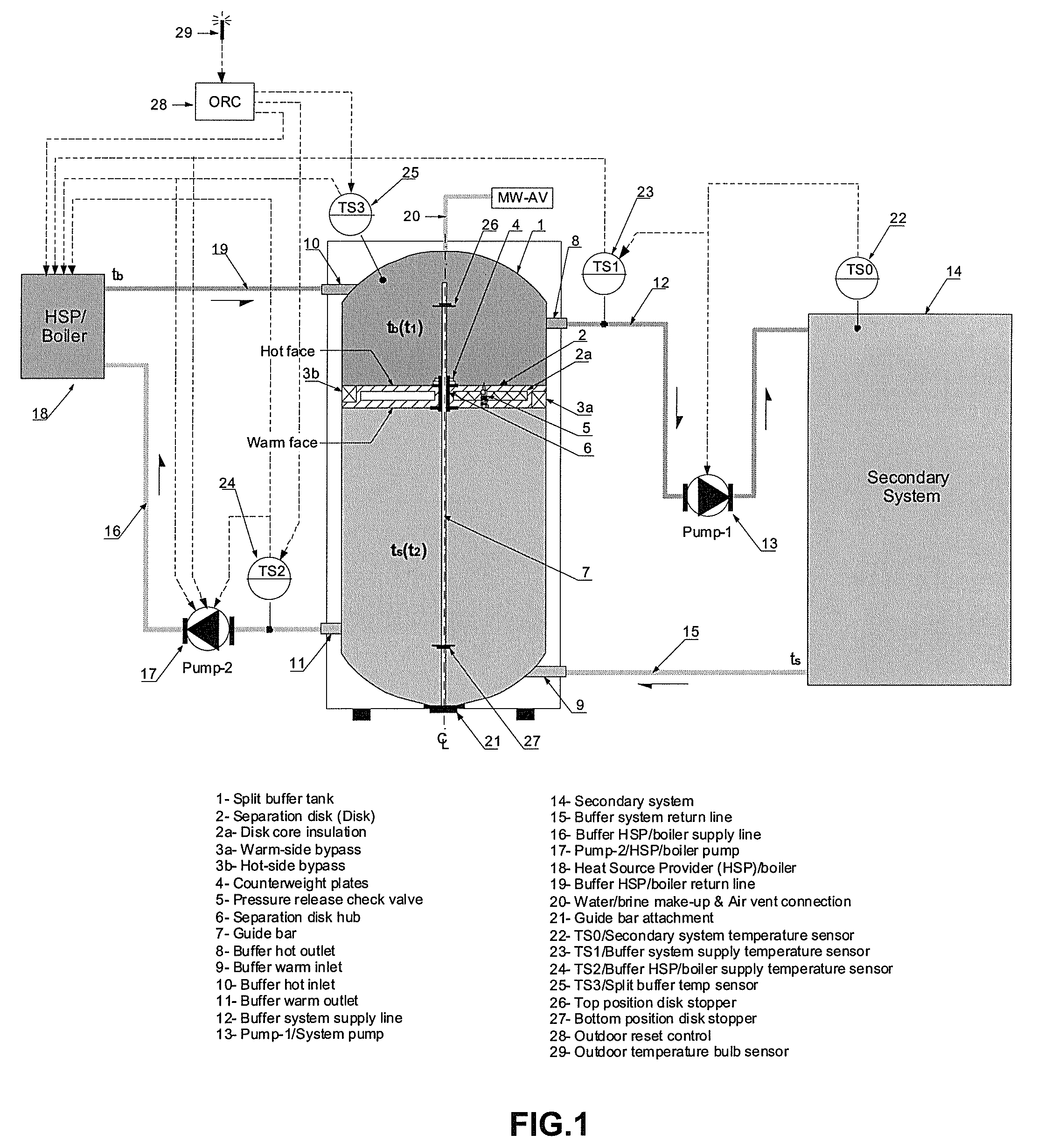
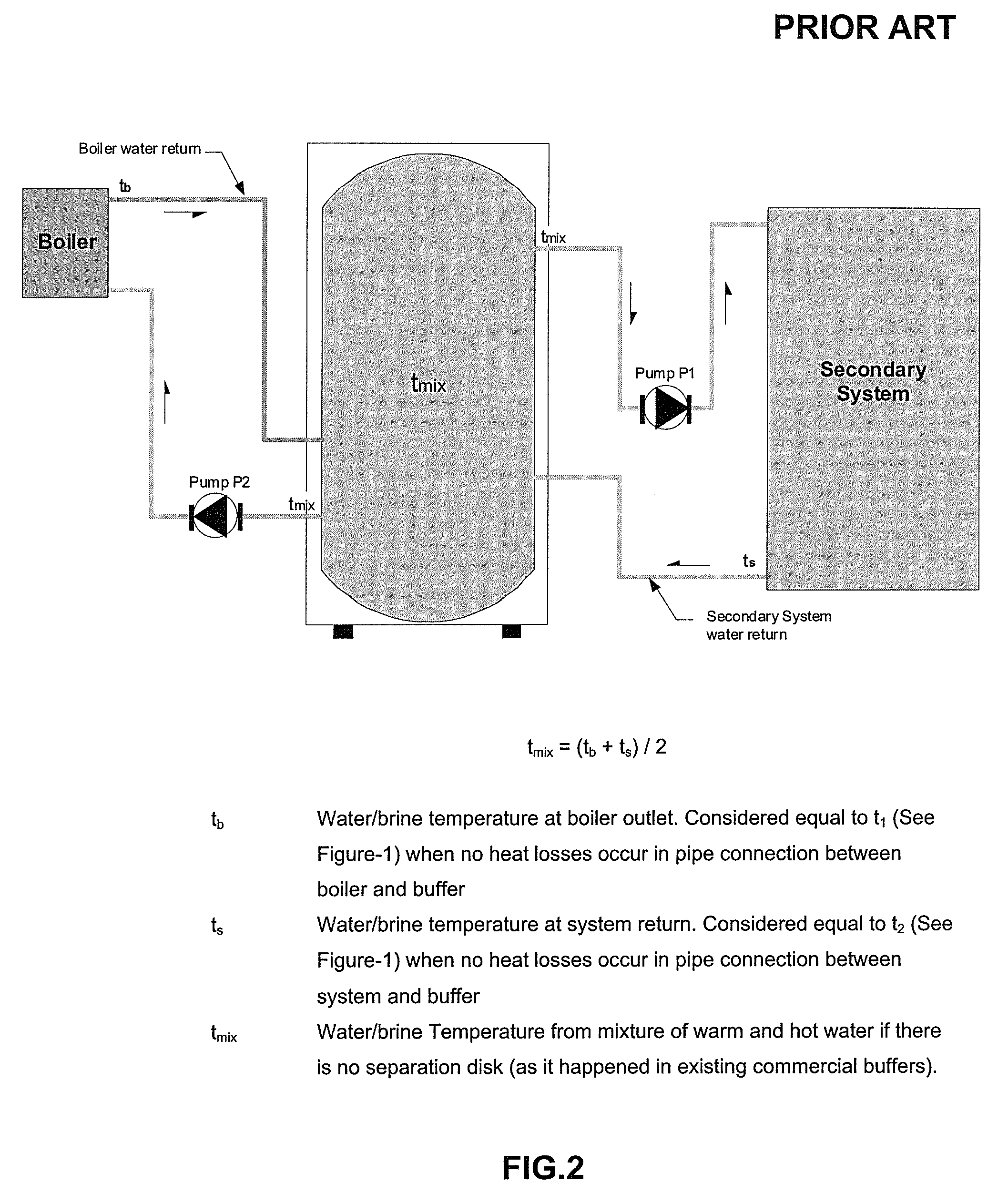
[0064]The present invention relates to a heating / cooling system operating on the basis of a SPLIT BUFFER TANK, as shown in FIG. 1. Its design includes a mechanical disk (2) in order to separate the hot HSP flow return (19) from the warm secondary system flow return (15). Because both sections get thermally and hydraulically isolated one from each other, it favours the separation of the two bodies of water with different thermal properties. This in turn, allows the independent supply of water / brine to the secondary system at a steady high temperature serving the demand for heat, and steady low water / brine temperature to the HSP for reheating. Since steady state conditions for both flows are possible with this new invention, its use will maximize thermal operating efficiency for existing large sets of manufactured HVAC equipment. It alone will allow not only the step down on equipment sizes for a given set of thermal conditions, but also the decrea...


PUM


Abstract

This invention relates to a heating / cooling system operating on the basis of a novel SPLIT BUFFER TANK; representing an efficiency improvement alternative to HVAC systems functioning with existing commercial buffer tanks. Currently, commercial buffers have the heat source provider (HSP)-return and system-return discharging to a common buffer / vessel. Novel SPLIT BUFFER is provided with a SEPARATION DISK placed inside the tank as mechanical way of separating the hot water inflow from the HSP from the warmer water inflow from system return. The disk moves up and down along the tank driven by demanded water supply and return. Pump-1 circulates hot water from the hot section of the buffer to the secondary system claiming for heat. Pump-2 circulates warmer water from the warmer section of the buffer through the HSP where it is reheated, and subsequently stored in the hot section of the buffer to reinitiate this cycle again.

Description

FIELD OF THE INVENTION[0001]The present invention relates generally to a heating / cooling system featuring a buffer tank, and more particularly to such a system employing a split buffer tank configured to separate hot heat source provider flow return from warm secondary system flow return.BACKGROUND OF THE INVENTION[0002]To better illustrate the nature of the invention, take for instance the case of a condensing boiler as a heat source provider (HSP). It is common to find all variety of brands and models operating at steady-state-efficiency levels from 70-80% for non-condensing to 82-98% for condensing. Steady-state Efficiency—refers to a measuring parameter for boiler maximum efficiency capability assessed under a controlled steady test and carried out by recognizable standard certification bureau. In the test, parameters such as air-intake temperature and volume, air / gas mixture, water / brine temperature / flow entering / leavening the boiler, system heat demand, and some others, are al...

Claims


Application Information

Patent Timeline
Patent Type & Authority Patents(United States)
IPC IPC(8): F24J2/04F24D11/00F24D11/02F24H9/12F28D20/00
CPCF24D11/004F24D11/0228F24H9/124F28D20/0039F24D2200/11F24D2200/12F28D2020/0095Y02B10/40Y02B10/70Y02E60/142Y02B30/126Y02B30/12Y02E60/14F24H9/133
Inventor BERRIO, DENERING
Owner BERRIO DENERING
Why Eureka
Try Eureka