Self-adaptive LED fluorescent lamp

a technology of led fluorescent lamps and power drives, which is applied in the direction of cathode-ray/electron beam tube circuit elements, instruments, lighting and heating apparatus, etc., can solve the problems of limited power, inability to embed the power supply in the aluminum tube case, and high replacement cost of the replacement of a traditional fluorescent lamp with an led lamp. achieve the effect of effective linear matching, low cost and low cos

Inactive Publication Date: 2015-04-07
NINGBO FUTAI ELECTRIC CO LTD
View PDF6 Cites 41 Cited by
  • Summary
  • Abstract
  • Description
  • Claims
  • Application Information

AI Technical Summary

Benefits of technology

[0004]The object of the present invention is to provide a self-adaptive LED fluorescent lamp with effective linear matching, small size, safety and reliability for use, low cost, and long service life, to overcome the above deficiencies in the prior art.
[0007]To achieve effective performance matching, reduce the cost and extend the service life of the circuit, the intelligent switching module comprises a first relay, a second relay and a field effect transistor, a grid end G of the field effect transistor is connected with a common end of the first resistor and the second resistor, a drain end D of the field effect transistor is connected with a negative end of the second relay, a source end S is connected with a negative output end of the rectifier filter module, the output of the intelligent switching module is connected with one or more LED lamp sets, in each lamp set, one or more LED lamps are connected in series, and each LED lamp is connected with one or more compensation resistors in series.
[0008]In order to improve the application safety and keep an Integrated Circuit (IC) away from too high power, the linear constant current module comprises two IC linear driving chips, the input end of each of the IC linear driving chips is connected with a second normally open end of the second relay, and the output end thereof is connected with the negative output end of the rectifier filter module.
[0009]To further achieve the performance matching and reduce cost, a first diode is connected between a first normally closed end of the first relay and a positive output end of the rectifier filter module, a first normally open end of the first relay is connected with the positive output end of the rectifier filter module, and a first LED lamp set and a second LED lamp set are in parallel connected between a second normally closed end of the first relay and the positive output end of the rectifier filter module; a third LED lamp set is connected between a second coil end and a first coil end of the first relay, and the common end of the third LED lamp set and the second coil end of the first relay is connected with a first normally closed end of the second relay; a third resistor and a third diode are in series connected between a positive voltage end of the first relay and the positive output end of the rectifier filter module, a fourth diode is connected between a negative voltage end of the first relay and the drain end of the field effect transistor, and a fourth LED lamp set is connected between a first normally open end of the second relay and a second normally closed end of the first relay; a first coil end of the second relay is connected with the second normally closed end of the first relay, a fifth LED lamp set is connected between a second normally open end of the second relay and the second coil end of the first relay, a sixth LED lamp set is connected between a second normally closed end of the second relay and the second coil end of the first relay, and a second diode is connected between the second normally closed end and the second normally open end of the second relay.
[0011]In the self-adaptive LED fluorescent lamp obtained by the present invention, a divider resistor R5 and a divider resistor R6 are connected behind the rectifier filter module to detect the output voltage of a rectifier. When the output voltage of the rectifier is normal, the voltage on R5 cannot reach the turn-on voltage of the field effect transistor Q, the positive output end of the rectifier filter module is directly connected to the first normally closed end of the relay, as the first normally closed end is connected with the first coil, the relay is turned on, so the circuit is turned on normally. When the output voltage rises, the voltage on the R5 correspondingly rises, so that Vgs (i.e., VR5) of the field effect transistor Q is turned on when a certain voltage value is reached to cause the relay to form a loop, converting the relay from TO-ON to TO-OFF, and changing the original parallel-series conversion, thereby automatically changing the number of the LED lamps in serial connection by automatically detecting the output voltage of the rectifier to reach the optimal driving efficiency, and achieving the advantages of effective linear matching, small size, safe and reliable application, low cost and long service life.

Problems solved by technology

Therefore, if there is a need to convert a traditional fluorescent lamp into an LED lamp with an external power supply, the wiring mode of the primary fluorescent lamp holder needs to be re-modified (because the driving mode of the LED is different from that of the traditional fluorescent lamp), resulting in technical difficulty and high replacement cost for the replacement of a traditional fluorescent lamp with an LED lamp.
Meanwhile, as a large-angle light emitting fluorescent lamp occupies ⅓ space of an aluminum tube, it is infeasible to embed the power supply in the aluminum tube case because the aluminum tube is low in height.
However, if such driving mode is adopted, the power supply has lots of deficiencies in power capacity and electrical appliance performance due to its limited length, such as, limited power, electromagnetic interference and high cost.
Because such power supply can be connected to commercial power voltage only, the linear matching capability is poor when a plurality of LEDs are driven with constant current.
However, with the consideration that too low efficiency or failure of constant current may be caused by voltage fluctuation in the practical application environment and that there are various fluorescent lamp rectifiers at present with varied output voltages, for example, rectifiers with 180VAC output and 130VAC output available in Japan, such driving circuit does not seem appropriate anymore.
Such driving circuit may cause insufficient driving voltage to the LED, thereby resulting in insufficient brightness or low brightness, reducing the application safety, and shortening the service life.

Method used


Image

  • Self-adaptive LED fluorescent lamp
  • Self-adaptive LED fluorescent lamp
  • Self-adaptive LED fluorescent lamp

Examples


embodiment

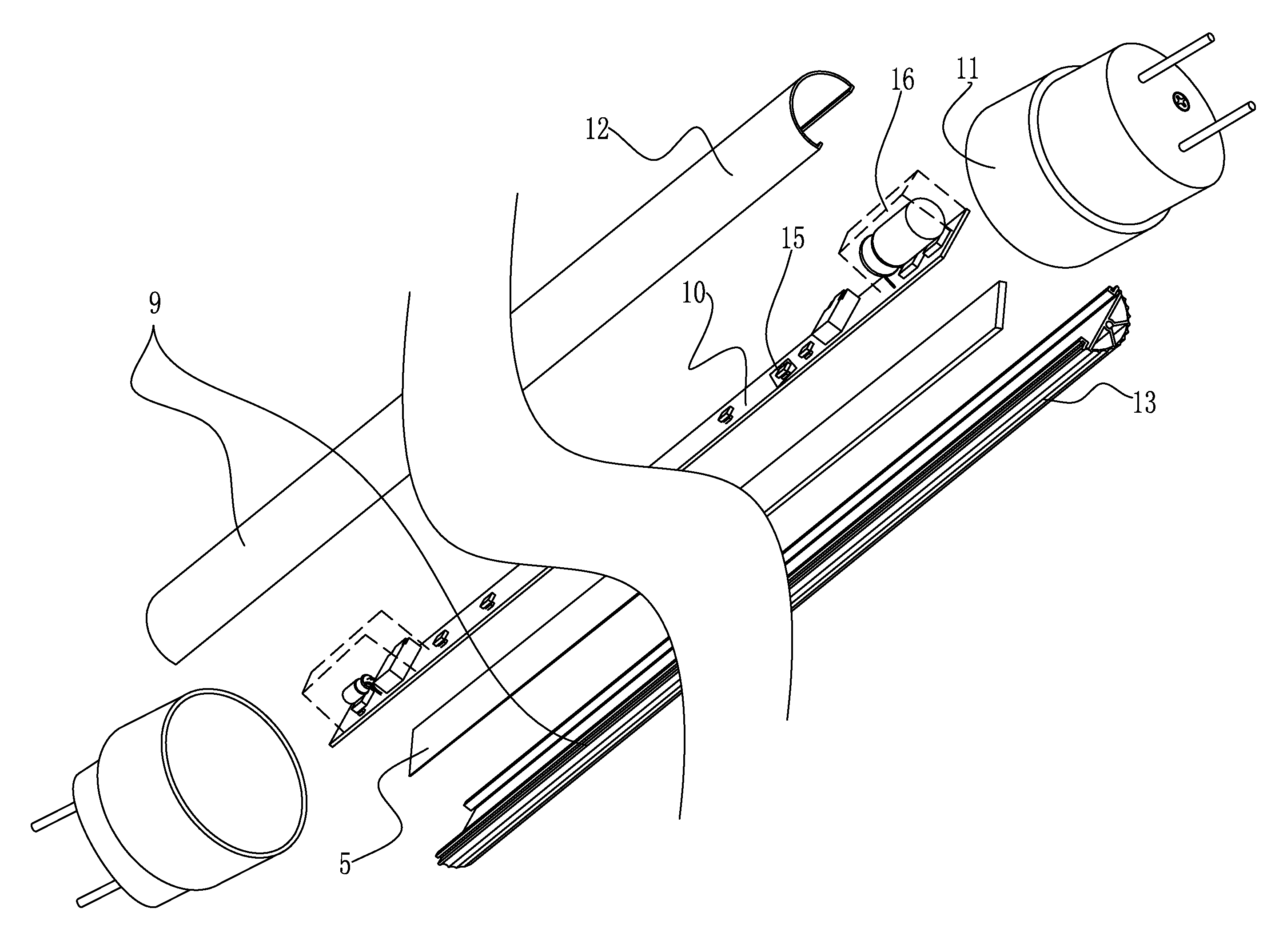
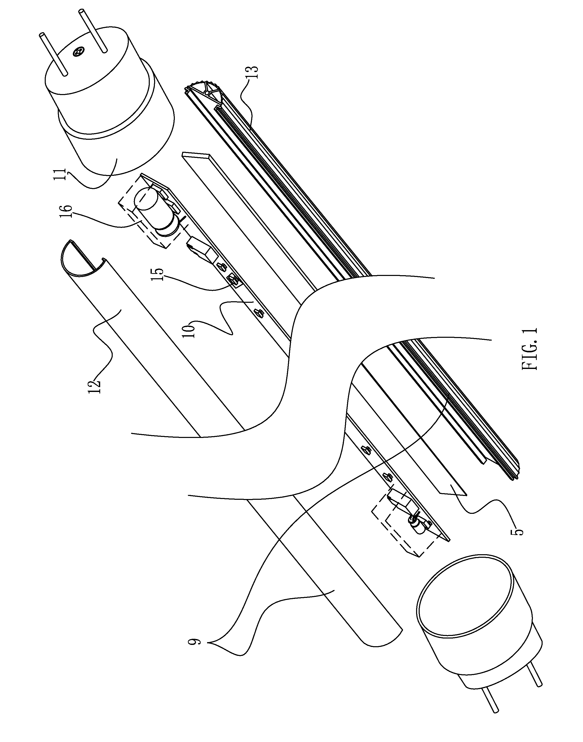
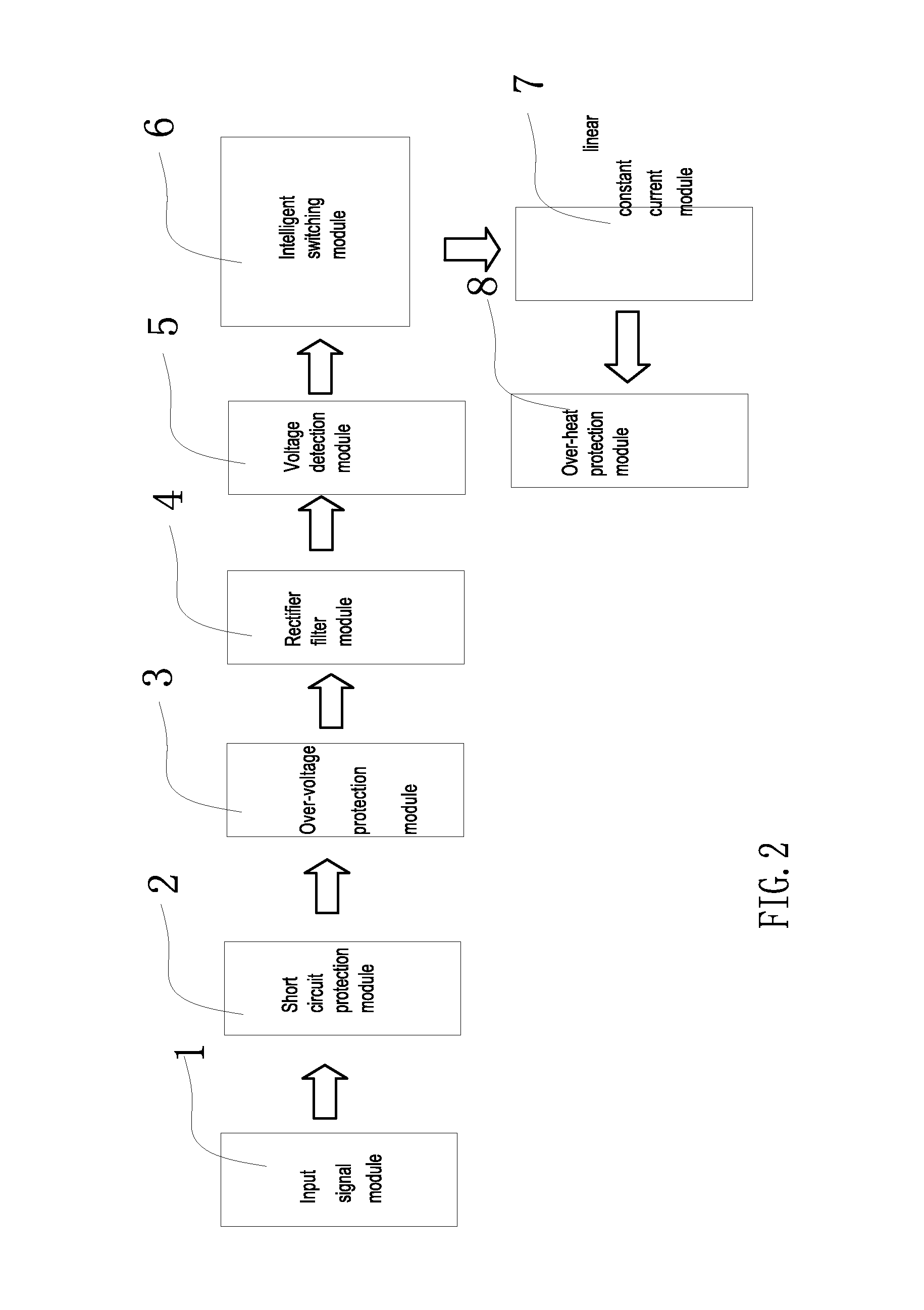
[0019]In FIG. 1, FIG. 2, and FIG. 3, the self-adaptive LED fluorescent lamp provided by the present invention comprises a housing 9, a PCB 10 and two lamp caps 11, the housing 9 comprises a lampshade 12 and a radiator 13 that are fastened with each other, each one of the two lamp caps 11 is sleeved on two sides of the housing 9, one or more LED lamp sets 15 and LED driving control units 16 are arranged on the PCB 10, a heat conductive double-sided silicone tape 14 is stuck between the PCB 10 and the radiator, the LED driving control unit 16 comprises an input signal module 1, a protection module and a rectifier filter module 4, the LED driving control unit 16 further comprises a voltage detection module 5 arranged behind the rectifier filter module 4 to detect and judge the voltage, an intelligent switching module 6 connected with the voltage detection module 5 to achieve intelligent switchover of the LED lamps, and a linear constant current module 7 connected with the intelligent s...


PUM


Abstract

The invention discloses an self-adaptive LED fluorescent lamp, comprising: a housing comprising a lampshade and a radiator fastened with each other, a Printed Circuit Board (PCB) consisting of one or more LED lamp sets and LED driving control units, and lamp caps sleeved on two sides of the housing; the LED driving control unit comprises a voltage detection module, an intelligent switching module and a linear constant current module; the voltage detection module comprises a first resistor and a second resistor, which are connected between two output ends of the rectifier filter module for voltage division, and a first capacitor connected with the second resistor in parallel; the intelligent switching module is connected with a common end of the first resistor and the second resistor, the output of the intelligent switching module is connected with a plurality of LED lamp sets, and each of the LED lamps is connected with a compensation resistor in series; and the linear constant current module consists of two IC linear driving chips. In the invention, the number of the LED lamps in serial connection is automatically changed by automatically detecting the output voltage of the rectifier, to reach the optimal driving efficiency, so as to ensure normal operating under any voltage.

Description

[0001]This is a U.S. national stage application of PCT Application No. PCT / CN2012 / 082596 under 35 U.S.C. 371, filed Oct. 8, 2012 in Chinese, claiming the priority benefit of Chinese Application No. 201210174370.8, filed May 31, 2012 in Chinese, which is hereby incorporated by reference.TECHNICAL FIELD[0002]The present invention relates to a power drive system of a fluorescent lamp, and in particular to a self-adaptive Light Emitting Diode (LED) fluorescent lamp.BACKGROUND[0003]The driving power supplies of fluorescent lamps in the current mainstream market are provided externally or embedded in an aluminum tube chase. LEDs have been widely applied in lighting due to its high light emitting efficiency, energy saving, long service life, adjustable brightness, safety, reliability and other advantages. Therefore, if there is a need to convert a traditional fluorescent lamp into an LED lamp with an external power supply, the wiring mode of the primary fluorescent lamp holder needs to be ...

Claims


Application Information

Patent Timeline
Patent Type & Authority Patents(United States)
IPC IPC(8): H01J7/44H05B37/02F21K99/00F21V29/00H05B44/00
CPCF21K9/175H05B33/0812F21V29/004H05B33/0824Y02B20/383Y02B20/386F21K9/278H05B45/395H05B45/44H05B45/00Y02B20/30H05B45/50F21V29/507F21V29/70
Inventor QIU, FUJUN
Owner NINGBO FUTAI ELECTRIC CO LTD
Why Eureka
Try Eureka