
Supporting structure for offshore wind power generator

a technology of supporting structure and generator, which is applied in the direction of machines/engines, artificial islands, mechanical apparatus, etc., can solve the problems of reducing price competitiveness, unable to obtain international certification, and reducing the contribution of bending resistance, so as to enhance rigidity and ductility of the structure, reduce the amount of material and weight, and reduce the effect of bending resistan

Active Publication Date: 2015-04-21
KOREA INST OF OCEAN SCI & TECH
View PDF22 Cites 2 Cited by
  • Summary
  • Abstract
  • Description
  • Claims
  • Application Information

AI Technical Summary

Benefits of technology

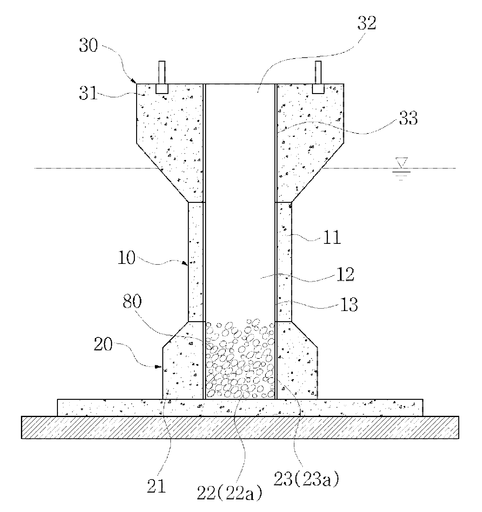
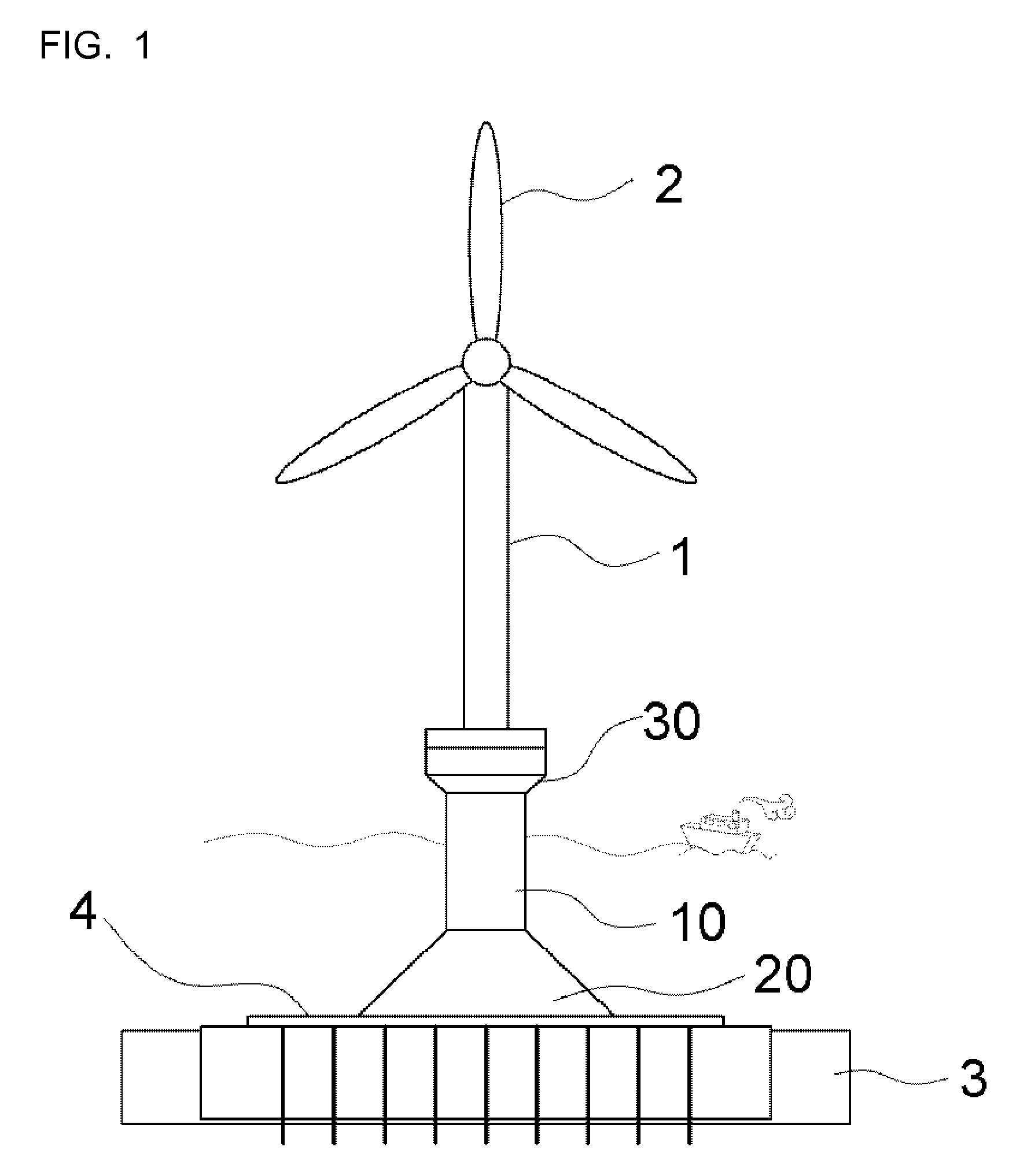
The present invention provides a supporting structure for offshore wind power generators that is lightweight, cost-efficient, and has superior rigidity and ductility to resist loading and bending movements. The structure includes a hollow space formed in the concrete parts to reduce weight, and reinforcing bars and the inner pipe are provided to prevent deterioration of ductility. The structure is assembled by two or more units, with shear keys and depressions provided to enhance structural strength of the junction between the units. The supporting structure can be produced by pre-casting and assembled in a site. Overall, the invention improves the construction and operation of offshore wind power generators.

Problems solved by technology

However, advanced countries do not open source core technology, making a technological gap between the advanced countries and other countries.
In the case of design criteria used in a design for civil engineering and construction structures, the systematic load of a wind power generator cannot be directly applied to these design criteria, so it is impossible to obtain international certification.
Further, in Korea, conservative and uneconomical design methods have been used, resulting in reduced price competitiveness, and making advance into the overseas markets difficult.
Therefore, related technical development is urgently required.
However, as such, if the volume of the supporting structure is large, the construction thereof cannot be facilitated, and excessive use of cement causes a problem of not being environment-friendly.

Method used


Image

  • Supporting structure for offshore wind power generator
  • Supporting structure for offshore wind power generator
  • Supporting structure for offshore wind power generator

Examples


first embodiment

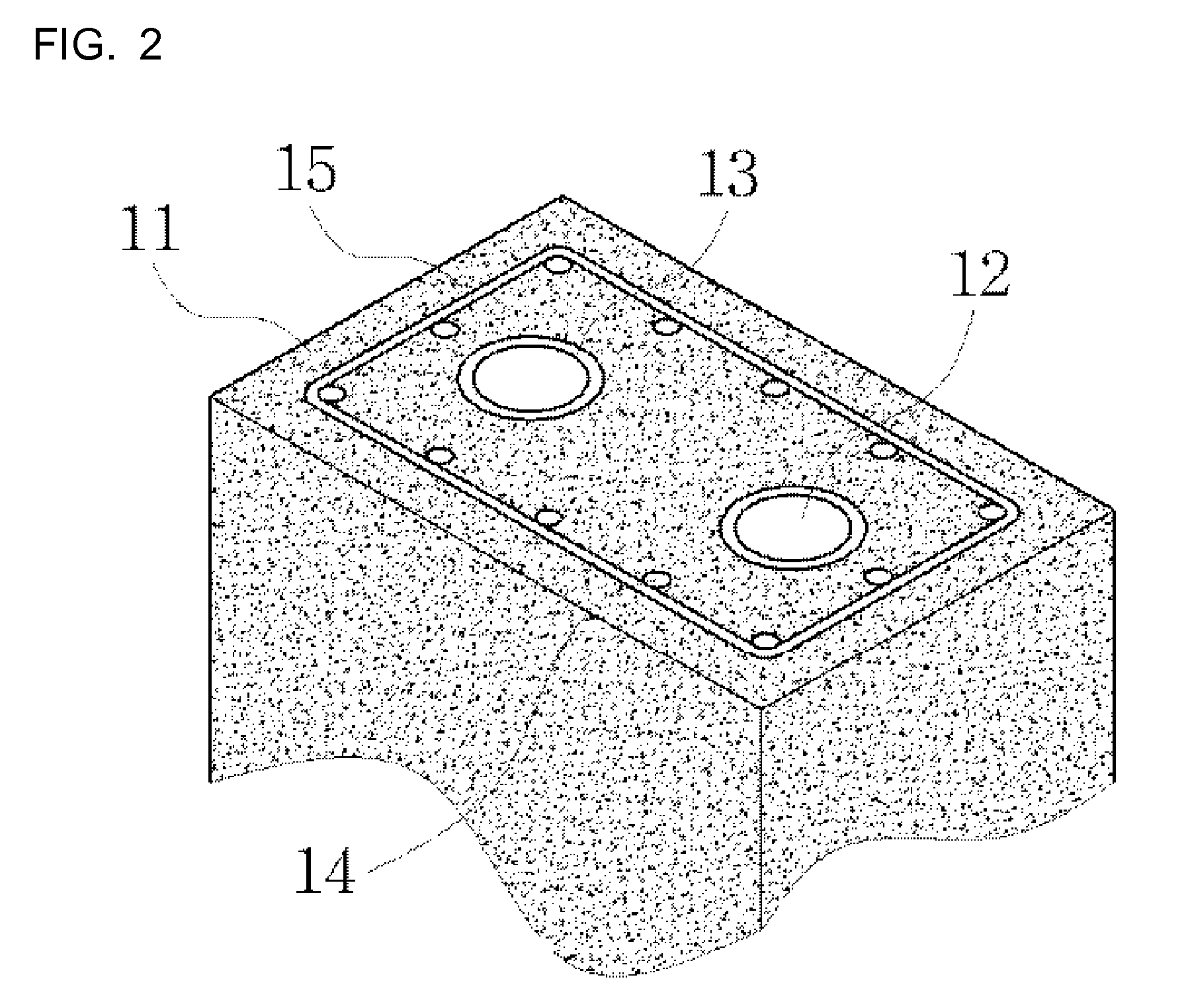
[0039]As shown in FIGS. 5A through 5C, in the first embodiment, a shear key 40a and a shear key depression 50a are provided in corresponding ends of the main-body concrete parts 11 of the units a that face each other. The shear key 40a has a protrusion shape and comprises a plurality of shear keys 40a. The shear key depression 50a comprises a plurality of shear key depressions 50a which correspond to the respective shear keys 40a. Facing each other, the shear keys 40a and the shear key depression 50a are provided in the main-body concrete parts 11 of the upper and lower units a so that the upper and lower units a can be assembled with each other in an insert coupling manner. In this case, different kinds of methods can be used to fasten the shear keys 40a and the shear key depressions 50a to each other and, for example, mortar may be used.

[0040]Preferably, the number of shear keys 40a and the number of shear key depressions 50a are changed in response to bending moment applied to a ...

third embodiment

[0042]FIGS. 7A through 7C illustrate the present invention. In this embodiment, a shear key 40c and a shear key depression 50c are provided in corresponding ends of the main-body concrete parts 11 of the units a, wherein the shear key 40c comprises a plurality of shear keys 40c each of which has a bar shape that protrudes from the main-body concrete part 11, and the shear key depression 50c comprises a plurality of shear key depressions 50c which are configured corresponding to the respective shear keys 40c so that the bar-shaped shear keys 40c are inserted into the respective shear key depressions 50c. In other words, each shear key 40c is a bar that is made of steel or the like and is inserted into or attached to an end of the main-body concrete part 11. An attaching end made of steel may be formed by the shear key 40c in the end of the main-body concrete part 11, although it is not designated by a reference numeral. In this case, each shear key depression 50c is formed by forming...

fourth embodiment

[0043]FIG. 8 illustrates the present invention. In this embodiment, a support 60 that has a plate shape is attached to a circumference of the junction J between the upper and lower units a so that the upper and lower units a can be coupled to each other. In detail, it is preferable that the plate-shaped support 60 be attached to the circumference of the junction J between the units a so as to prevent the junction J between the units from becoming brittle.

[0044]The support 50 is attached to the junction J between the units a and is preferably made of FRP because it must have corrosion resistance. A known technique, for example, using adhesive, can be used to attached the support 50 to the junction J between the units a and, therefore, further explanation thereof will be omitted.

[0045]FIGS. 9A and 9B illustrate another embodiment. In this embodiment, a connector 70 that has an H-shaped cross-section is provided in the junction J between the upper and lower units a so as to fasten the ...


PUM


Abstract

Disclosed herein is supporting structure for an offshore wind power generator. The supporting structure includes lower support part and main body part. The lower support part includes lower concrete part which is provided on a base installed on the sea floor and is reduced in width from the bottom thereto to the top, at least one lower hollow space which is formed in the lower concrete part, and a lower inner-pipe which is attached to the inner surface of the lower hollow space. The main body part is coupled to an upper end of the lower support part. The main body part includes a main-body concrete part, at least one main-body hollow space which is formed in the main-body concrete part and communicates with the lower hollow space, and a main-body inner-pipe which is attached to a circumferential inner surface of the main-body hollow space.

Description

[0001]This application claims foreign priority of Korean Patent Application No. 10-2012-0104697, filed on Sep. 20, 2012 which is incorporated by reference in its entirety into this application.BACKGROUND OF THE INVENTION[0002]1. Field of the Invention[0003]The present invention relates generally to supporting structures for offshore wind power generators and, more particularly, to a supporting structure for offshore wind power generators which includes a lower support part, a main body part and an upper support part, each of which has a concrete part, a hollow space formed in the concrete part, and an inner pipe that defines the hollow space, wherein the inner pipe can improve the rigidity and ductility of each part, thus enhancing resistance to transverse loads at sea, and the hollow space of each part can reduce the weight thereof, and the parts of the supporting structure can be modularized so that the supporting structure can be constructed by assembling the parts, whereby there...

Claims


Application Information

Patent Timeline
Patent Type & Authority Patents(United States)
IPC IPC(8): E02B17/02E02B17/00F03D11/04
CPCE02B17/025F03D11/045Y02E10/727E02B2017/0091F05B2240/95F03D13/22Y02E10/72E02B17/02E02D27/52F03D13/20
Inventor HAN, TAEK HEEPARK, WOO SUNWON, DEOK HEE
Owner KOREA INST OF OCEAN SCI & TECH
Learn More