Dielectrophoretic cooling solution for electronics

a cooling solution and electronics technology, applied in the direction of electrical equipment, lighting and heating equipment, instruments, etc., can solve the problems of increasing the heat flux generated by electronic devices, and increasing the cost of passive cooling

Active Publication Date: 2015-05-12
HAMILTON SUNDSTRAND CORP
View PDF15 Cites 0 Cited by
  • Summary
  • Abstract
  • Description
  • Claims
  • Application Information

AI Technical Summary

Problems solved by technology

The thermal management of electronics presents a large and growing challenge.
High power density electronics result in an increase in the heat flux generated by electronic devices, such that passive cooling may no longer be sufficient.
Thermal management limitations are beginning to present a ceiling from electronics reaching full capacity.
As an example, clock speeds on central processing units have been reduced, and the power rating for power electronic components has been restricted.
The theoretical operating limits of the electronic devices far exceed what is possible to implement with present cooling solutions.
Fluid pumping has been proposed, however, most mechanical pumps raise reliability issues, and can introduce noise, vibration and other challenges.

Method used


Image

  • Dielectrophoretic cooling solution for electronics
  • Dielectrophoretic cooling solution for electronics

Examples


Embodiment Construction

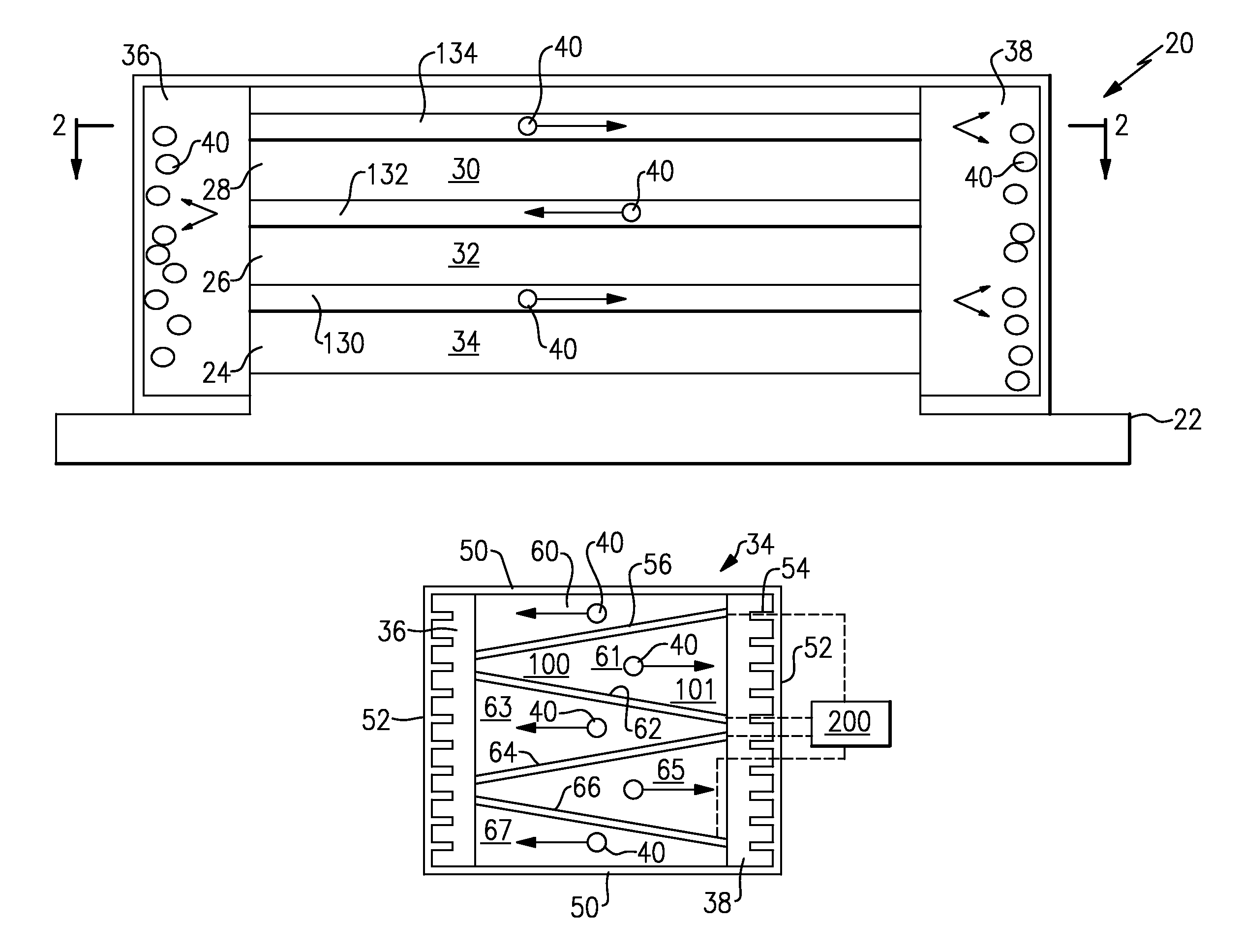
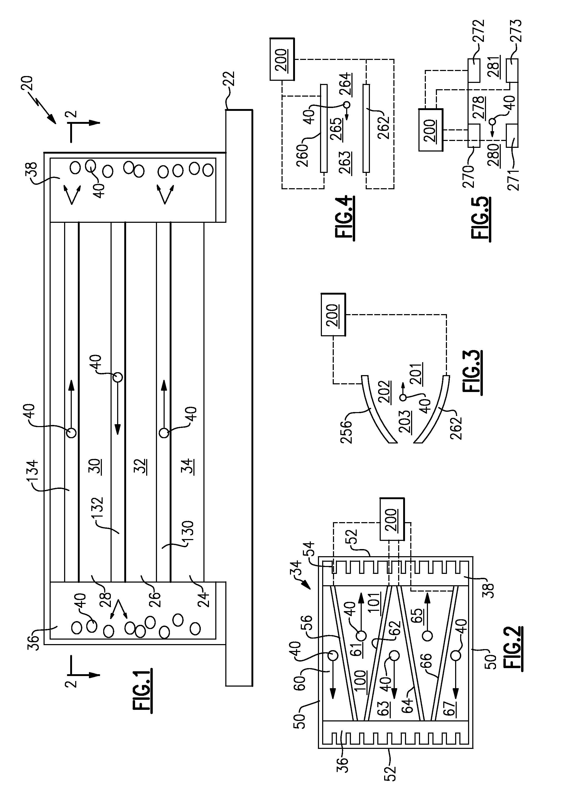
[0013]FIG. 1 shows a stack 20 that mounts a plurality of electronic controls or cores 30, 32 and 34. On the other hand, this application would extend to a single cooling layer cooling a single control element. As disclosed, these may be electronic control elements, such as central processing units or power controllers, or any other component that requires cooling. The cores 30, 32, 34 are all generally planar.

[0014]Micro-channel cooling channels are defined at 130, 132 and 134, and intermediate the cores 30, 32, and 34. In a sense, the channels 130, 132, 134 and cores 30, 32, 34 are stacked in a direction generally perpendicular to the planar shape of the cores 30, 32, 34. Of course, the cores 30, 32, 34 are not actually planar.

[0015]End plenums 36 and 38 are defined at axial ends of the cooling channels 130, 132 and 134. A cold plate 22 is placed adjacent a lower most one of the cores 24, and operates to tap heat away. Another type heat sink can replace cold plate 22.

[0016]As shown...


PUM


Abstract

At least one cooling channel is positioned adjacent to an electronic component. The cooling channel communicates with plenums at each of two opposed axial ends. A dielectric fluid is received in the cooling channel. The cooling channel is provided with at least one electrode. A potential is applied to the at least one electrode such that an electric field magnitude at the downstream end of the channel is less than an upstream electric field magnitude, and such that a dielectrophoretic force on a bubble in the cooling channel will force it downstream.

Description

BACKGROUND OF THE INVENTION[0001]This application relates to the use of dielectrophoretic forces to cool electronic components.[0002]The thermal management of electronics presents a large and growing challenge. High power density electronics result in an increase in the heat flux generated by electronic devices, such that passive cooling may no longer be sufficient. Thermal management limitations are beginning to present a ceiling from electronics reaching full capacity.[0003]As an example, clock speeds on central processing units have been reduced, and the power rating for power electronic components has been restricted. The theoretical operating limits of the electronic devices far exceed what is possible to implement with present cooling solutions.[0004]Fluid pumping has been proposed, however, most mechanical pumps raise reliability issues, and can introduce noise, vibration and other challenges.[0005]Dielectrophoretic pumping is known, and has been proposed for some application...

Claims


Application Information

Patent Timeline
Patent Type & Authority Patents(United States)
IPC IPC(8): H01L23/34H05K7/20F28F7/00G06F1/20H01L23/473
CPCH05K7/20327H05K7/20936H01L23/473G06F1/20H05K7/20272G06F2200/201H01L2924/0002H01L2924/00H05K7/20254
Inventor PEARSON, MATTHEW ROBERTST. ROCK, BRIAN
Owner HAMILTON SUNDSTRAND CORP
Why Eureka
Try Eureka