
Amplified backscatter x-ray inspection system

Active Publication Date: 2015-05-19
THE BOEING CO
View PDF5 Cites 11 Cited by
  • Summary
  • Abstract
  • Description
  • Claims
  • Application Information

AI Technical Summary

Benefits of technology

The patent describes a device that emits radiation and detects the backscatter that occurs when the radiation meets an object. The device also redirects the backscatter to the detection system using a separate system. The technical effect of this invention is improved detection and analysis of objects using multiple sources of radiation and a system for redirecting the backscatter.

Problems solved by technology

This distribution of x-ray photons increases the difficulty in designing a detector for detecting backscatter x-ray photons as efficiently as desired.
This larger power supply usually results in a larger x-ray tube.
The increase in the size of the power supply and the x-ray tube increases the expense, size, and weight of the backscatter x-ray inspection system.

Method used


Image

  • Amplified backscatter x-ray inspection system
  • Amplified backscatter x-ray inspection system
  • Amplified backscatter x-ray inspection system

Examples


Embodiment Construction

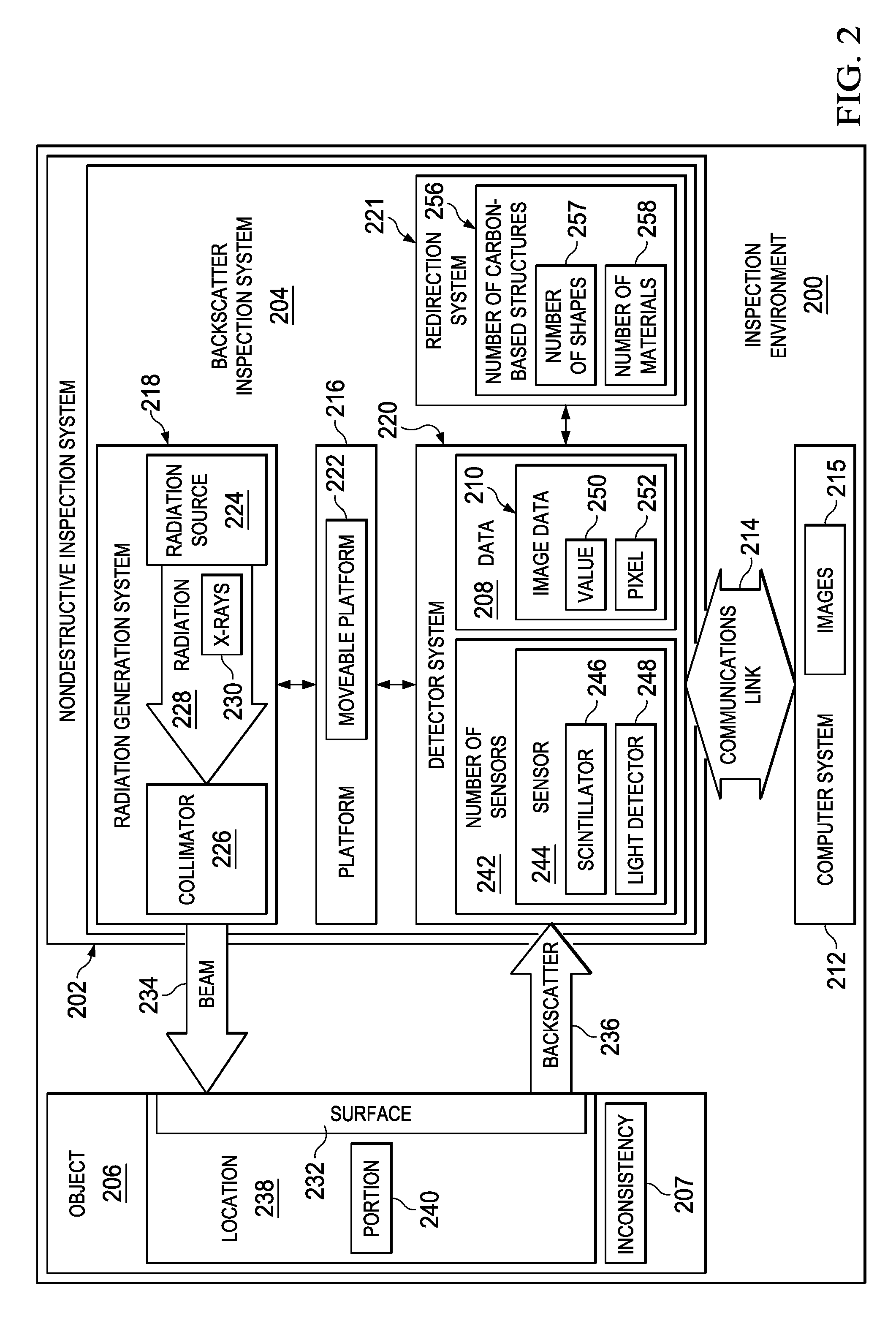
[0031]The illustrative embodiments recognize and take into account one or more different considerations. For example, the illustrative embodiments recognize and take into account that a good detector for detecting x-ray photons in backscatter is a detector that detects x-ray photons in a larger range of energy levels than currently possible. For example, it would be desirable to have a detector that may detect x-ray photons that are scattered from the low end through the high end in a spectrum of levels of x-ray energy in a Bremsstrahlung x-ray distribution.

[0032]The illustrative embodiments recognize and take into account that many detection systems are used to count the number of x-ray photons in the backscatter from a particular location. With these types of systems, counting an x-ray photon more than once is undesirable.

[0033]The illustrative embodiments also recognize and take into account that with respect to generating images, the concern with counting x-ray photons may be ab...


PUM


Abstract

A method and apparatus for inspecting an object. A radiation generation system is configured to emit radiation. A detector system is configured to detect backscatter formed in response to the radiation encountering the object. A redirection system is positioned relative to the detector system and is configured to redirect the backscatter to the detector system.

Description

BACKGROUND INFORMATION[0001]1. Field[0002]The present disclosure relates generally to inspection systems and, in particular, to backscatter x-ray inspection systems. Still more particularly, the present disclosure relates to a method and apparatus for increasing the amount of backscatter detected off of an object.[0003]2. Background[0004]A backscatter x-ray inspection system is an example of a nondestructive inspection system that uses x-rays to inspect an object. Some currently available backscatter x-ray inspection systems include an x-ray tube, a collimator, and a detector. The x-ray tube generates and emits x-rays. The collimator filters these x-rays to form an x-ray beam using a portion of the x-rays that travel substantially parallel to a specified direction.[0005]When the x-ray beam encounters the object, some or all of the x-rays in the x-ray beam are not absorbed by the object. Some or all of the x-rays may be scattered by the object. In particular, the x-rays may be scatte...

Claims


Application Information

Patent Timeline
IPC IPC(8): G01N23/201G01N23/00
CPCG01N23/00G01N23/203G01N2223/1016G01N2223/631G01N2223/645
Inventor SAFAI, MORTEZA
Owner THE BOEING CO
Features
  • Generate Ideas
  • Intellectual Property
  • Life Sciences
  • Materials
  • Tech Scout
  • Unparalleled Data Quality
  • Higher Quality Content
  • 60% Fewer Hallucinations
Learn More